Heat exchanger

A technology for heat exchangers and refrigerators, applied in heat exchange equipment, heat exchanger shells, indirect heat exchangers, etc., can solve problems such as high cost

Active Publication Date: 2013-09-25
MAHLE INT GMBH
View PDF8 Cites 50 Cited by
  • Summary
  • Abstract
  • Description
  • Claims
  • Application Information

AI Technical Summary

Problems solved by technology

In addition, high costs are required in the manufacture of heat exchangers with thermal expansion valves

Method used


Image

  • Heat exchanger
  • Heat exchanger
  • Heat exchanger

Examples


Embodiment Construction

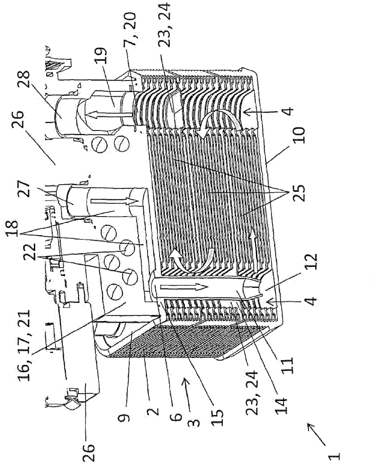
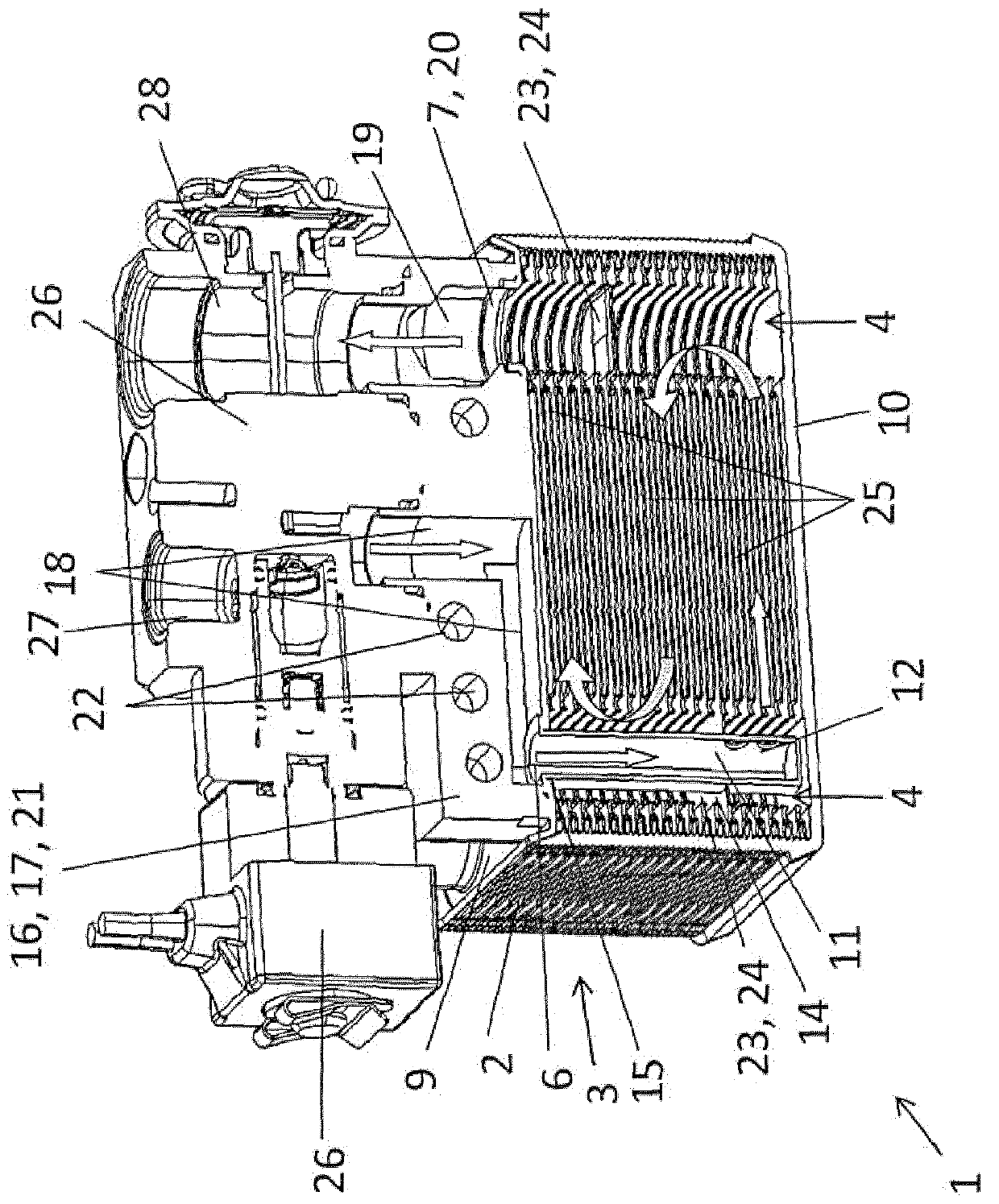
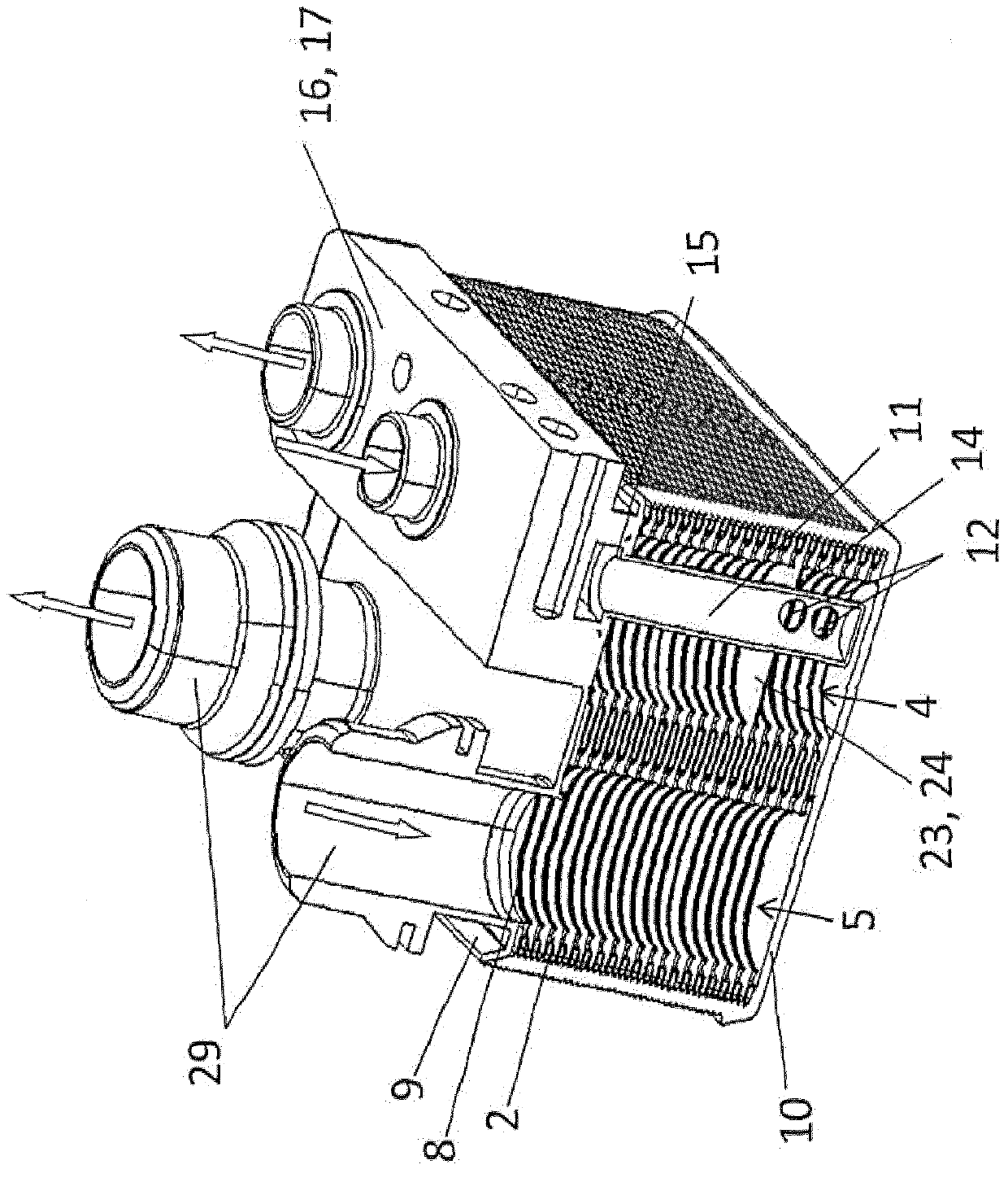
[0082] In the side view of FIG. 1 , the shown heat exchanger 1 or cooler 1 is installed in a not shown system for heating and / or cooling the battery of a vehicle (as a hybrid or electric vehicle). The heat exchanger 1 is designed here as a heat exchanger 1 in the form of a laminate. A plurality of stacked sheets 2 with first and second notches 4 , 5 or holes 4 , 5 are stacked vertically to form a stack 3 . Thus, a first fluid channel and a second fluid channel may be provided between the stacked sheets 2 for conveying fluid. Thus, heat can be transferred from the first fluid to the second fluid, or vice versa. The first opening 4 likewise forms a first fluid channel through which a first fluid flows into and out of the first fluid channel between the stacked lamellae 2 . This also applies analogously to the second fluid channel or second opening 5 . According to the illustration in FIG. 1 , the stack 3 of stacked sheets 2 is closed at the upper end by a cover 9 and the stac...


PUM


Abstract

In a plate-type heat exchanger (1) or chiller (1), comprising a multiplicity of stacking plates (2) stacked one on top of the other such that a first fluid duct for a first fluid and a second fluid duct for a second fluid are formed between the stacking plates (2), the stacking plates (2) having first apertures (4) as a first fluid duct for the supply and discharge of the first fluid, the stacking plates (2) having second apertures (5) as a second fluid duct for the supply and discharge of the second fluid, at least one diverting device (23) which closes off at least one first aperture (4) such that the first fluid is conducted in meandering manner through at least two, preferably at least three sections (25) of the first fluid duct between the stacked plates (2) in the opposite direction through the heat exchanger (1), a first inlet and outlet opening (6, 7); for conducting in and discharging the first fluid, and a second inlet and outlet opening for conducting in and discharging the second fluid, it is the aim for the heat exchanger (1) to be as compact as possible and to be simple and cheap to produce. Said problem is solved in that the first inlet or outlet opening (6, 7) is formed by an immersion pipe (11) and the first fluid can be conducted into the first fluid duct through the immersion pipe (11), such that the first inlet and outlet openings (6, 7) are formed on the same side of the heat exchanger (1).

Description

technical field [0001] The invention relates to a heat exchanger according to the preamble of claim 1 and to a system for heating and / or cooling a battery of a motor vehicle according to the preamble of claim 14 and to A vehicle air-conditioning device according to the preamble of claim 15 . Background technique [0002] The battery of a hybrid or electric vehicle must be heated or cooled to obtain the proper operating temperature for the battery (for example in the temperature range between 0°C and 40°C). When power is drawn from or charged to a battery, the battery emits heat, so the battery must be cooled so that it does not heat up to temperatures exceeding 30°C or 40°C. At low external temperatures, for example below 0° C., the battery must be heated so that electrical energy can be extracted from the battery and charged. For this purpose, hybrid or electric vehicles have a coolant circuit by means of which the battery can be cooled and preferably heated. [0003] DE...

Claims


Application Information

Patent Timeline
Patent Type & Authority Applications(China)
IPC IPC(8): F28D9/00F28F9/02B60H1/00F25B39/02H01M10/50
CPCF25B39/022F28D1/0325F28D9/005F28F9/0268F28F27/02H01M10/625H01M10/663H01M10/613F25B2500/18Y02E60/10F25B41/31B60H1/3227B60H1/3229B60H1/00H01M10/60
Inventor 马库斯·韦斯纳汉斯-乔治·赫里曼彼得·克莱因托马斯·希莫
Owner MAHLE INT GMBH
Why Eureka
Try Eureka