Antenna device and communication device

An antenna device, information communication technology, applied in the direction of antenna, loop antenna, electric long antenna, etc., to achieve good communication characteristics and high degree of freedom

Inactive Publication Date: 2013-09-25
DEXERIALS CORP
View PDF9 Cites 1 Cited by
  • Summary
  • Abstract
  • Description
  • Claims
  • Application Information

AI Technical Summary

Problems solved by technology

In addition, since the metal wire 207 needs to connect the coupling electrode 208 and the stub 203 at a predetermined position, there are also problems in the process of requiring positional alignment accuracy during production.

Method used


Image

  • Antenna device and communication device
  • Antenna device and communication device
  • Antenna device and communication device

Examples


no. 1 Embodiment approach

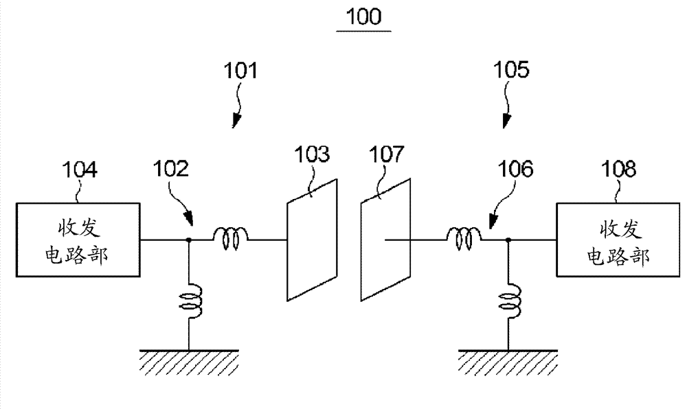
[0049] As an antenna device incorporated in such a communication system 100, for figure 2 The high-frequency coupler 10 of the first embodiment as shown will be described.

[0050] exist figure 2 In the figure, in order to easily understand the connection state of the line 12 and the ground 13 described later, it is shown through the protective film 15 .

[0051] Such as figure 2 As shown, the high-frequency coupler 10 has a structure in which a ground 13 is formed on one surface of a dielectric substrate 11 and ring-shaped wires 12 are formed at a constant distance on the outer periphery thereof.

[0052] The wire 12 functions as a coupling electrode 17 , and one end of the wire 12 faces the ground 13 to serve as the power supply unit 14 to be connected to the above-mentioned transmission and reception circuit unit 104 , and the other end of the wire 12 is electrically connected to the ground 13 . In addition, the wiring length of the wire 12 functioning as the coupling...

no. 2 Embodiment approach

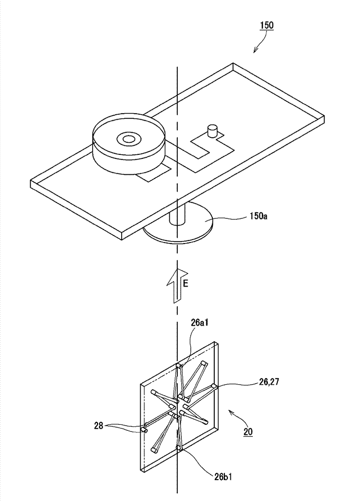
[0073] Next, as an antenna device incorporated in such a communication system 100, for Figure 6 The high-frequency coupler 20 of the second embodiment as shown will be described.

[0074] exist Figure 6 In the figure, in order to easily understand the winding state of the coil 26 described later, it is shown through the dielectric substrate 21 .

[0075] The high-frequency coupler 20 includes a dielectric substrate 21 and a coil 26 electrically connecting coils 26a and 26b each having a length approximately equal to 1 / 2 of the communication wavelength, and connections to the transceiver circuit unit 104 are formed at both ends of the coil 26. The connection terminal 28 is used. In the coil 26, the signal levels are mutually reversed in polarity at the line center portions 26a1, 26b1 of the coils 26a, 26b, that is, at positions separated by 1 / 4 and 3 / 4 of the communication wavelength from one end of the coil 26. becomes high in the state of , and functions as the coupling ...


PUM


Abstract

Provided is an antenna device that enables the realization of both good communication characteristics and good mechanical strength and that has a structure that is favourable to both small size and low profiling. The antenna device, which communicates information by coupling the electromagnetic fields between a pair of opposing electrodes by using a prescribed communication wavelength, comprises a coupling electrode (17) that is formed on a dielectric substrate (11) and that becomes communicable by electromagnetic coupling with an electrode of another antenna device. The coupling electrode (17) has a line (12) that is half the length of the communication wavelength and is formed on the dielectric substrate (11), and a ground (13) that opposes the line center (12a) of the line (12) and the surface direction of the dielectric substrate (11) and that is electrically connected to the line (12). The coupling electrode electromagnetically couples with an electrode of another antenna device disposed on an extended line connecting the line center (12a) and the ground (13).

Description

technical field [0001] The present invention relates to a communication device that performs information communication by performing electromagnetic field coupling between a pair of opposing electrodes using a predetermined communication wavelength, and a communication device incorporating the antenna device. [0002] This application claims priority based on Japanese Patent Application No. 2011-023048 filed on February 4, 2011 and Japanese Patent Application No. 2011-148566 filed on July 4, 2011 in Japan, and is incorporated by reference These applications are hereby incorporated by reference into the present application. Background technique [0003] In recent years, systems for wirelessly transmitting data such as music and images are being developed between electronic devices such as computers and small portable terminals without using cables or media. Among such wireless transmission systems, there is a wireless transmission system capable of realizing high-speed trans...

Claims


Application Information

Patent Timeline
Patent Type & Authority Applications(China)
IPC IPC(8): H01Q7/00H01Q1/38H01Q11/04H04B5/02
CPCH01Q1/38H01Q7/00H04B5/0012H04B5/0031H01Q11/04
Inventor 久村达雄
Owner DEXERIALS CORP
Why Eureka
Try Eureka