
Ultralow belt conveyer

A belt conveyor, ultra-low technology, applied in the direction of conveyors, conveyor objects, transportation and packaging, etc., can solve the problems of ultra-low working space, increase the travel length of the belt conveyor, and not easy to achieve reduction The effect of working height

Inactive Publication Date: 2013-10-02
ZHENGZHOU DINGLI DRYING EQUIP
View PDF9 Cites 2 Cited by
  • Summary
  • Abstract
  • Description
  • Claims
  • Application Information

AI Technical Summary

Problems solved by technology

[0003] Although this kind of implementation can complete material transportation, it has the following disadvantages: 1. The volume of the general belt conveyor itself is large, and the height of the belt conveyor needs to be dug to be installed in an ultra-low working space. It is not easy to move the belt conveyor out of the working area, which causes great trouble for repair and maintenance; 2. Since the ultra-low working space is very small, in order to facilitate daily maintenance, the pit dug must have sufficient area and depth, which is relatively small. Large ones consume more manpower and material resources; 3. The equipment is arranged in a deep pit, which is inconvenient for installation and maintenance; 4. The belt conveyor has a climbing angle requirement, and the maximum cannot exceed 22 degrees. The deep pit increases the lifting height of the material, thereby increasing the stroke length of the belt conveyor, which increases the manufacturing cost and operating cost of the conveyor; 5. The increase in the stroke length of the belt conveyor increases the use area and cost of the site accordingly

Method used


Image

  • Ultralow belt conveyer
  • Ultralow belt conveyer
  • Ultralow belt conveyer

Examples


Embodiment Construction

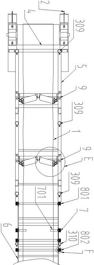
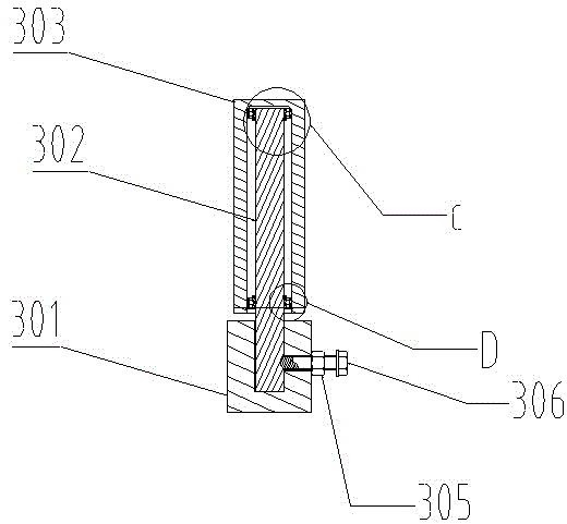
[0032] An ultra-low belt conveyor, such as figure 1 , 2 , 3, 4, 5, 6, 7, 8, 9, 10, including a frame, a belt 1, a belt support device 9, a tensioning device 2, and a power device. The frame includes an upper frame 5 and a lower frame Frame 6, the upper frame is inclined, the lower frame is horizontal, the angle between the upper frame and the lower frame is 21°, the upper frame and the lower frame They are all tailor-welded by a number of supporting steel plates, foot joints, round steel, etc., and play the role of supporting and fixing the belt; the power device is the electric drum 4, which is set on the upper frame through the electric drum bearing seat 401 The upper; the intersection of the lower frame and the upper frame is provided with a belt pressing shaft device 7 that compresses the belt and forms an elevation turn. The belt pressing shaft device includes a pair of pressing shaft fittings, a pair of pressing The belt-shaft joints are respectively arranged on both side...


PUM


Abstract

The invention relates to an ultralow belt conveyer. The ultralow belt conveyer comprises a machine frame, a conveying belt, a belt supporting device, a tensioning device and a power device, wherein the machine frame comprise an upper machine frame and a lower machine frame, the upper machine frame is arranged obliquely, the lower machine frame is arranged horizontally, the included angle between the upper machine frame and the lower machine frame is smaller than 22 degrees, a belt pressing shaft device is arranged at the junction between the lower machine frame and the upper machine frame, the conveying belt is tightly pressed by the belt pressing shaft device and elevation steering is achieved, the belt pressing shaft device comprises a pair of belt pressing shaft fittings, the belt pressing shaft fittings are arranged at the two sides of the conveying belt respectively, the length of each belt pressing shaft is far smaller than the width of the conveying belt, and each belt pressing shaft fitting comprises a belt pressing shaft, a bearing and a bearing seat. The ultralow belt conveyer further comprises a rotary shaft fitting and a belt blocking device, wherein the rotary shaft fitting is used for bearing the weight of the conveying belt and limiting the travel distance of the conveying belt, and the belt blocking device is used for correcting the deviation of the conveying belt. The ultralow belt conveyer has the advantages that the size is small, the weight is low, no pit needs to be dug on the ground, and the belt conveyer can be moved manually.

Description

Technical field [0001] The invention relates to the field of material transportation, in particular to the material transportation that completes receiving and transporting materials in an ultra-low working space, and in particular to an ultra-low belt conveyor. Background technique [0002] High and heavy equipment should not be placed in a high position. It is generally placed in contact with the ground, and the feet of this type of equipment are generally low. When the equipment has a discharge and flows out from the bottom, the outflow of the material will form a super low This ultra-low material transportation space can be referred to as ultra-low working space. The material transportation in the ultra-low working space generally uses belt conveyors. The layout of the belt conveyor in the ultra-low working space has become an important issue. The traditional method is to dig on the ground directly below the ultra-low working space. The belt conveyor is placed in the pit to ...

Claims


Application Information

Patent Timeline
Patent Type & Authority Applications(China)
IPC IPC(8): B65G15/00B65G15/60B65G23/44B65G21/20B65G39/02B65G39/09
Inventor 李留纪罗刚银张志宇刘彦辰訾伟旗高素玲周云飞朱甲哲符新国
Owner ZHENGZHOU DINGLI DRYING EQUIP
Learn More