Condenser steam injection vacuum system

A vacuum system and condenser technology, applied in jet pumps, machines/engines, non-displacement pumps, etc., can solve problems such as the temperature of the working fluid cannot be cooled to the design value, and achieve high reliability, simple operation, and simple system Effect

Inactive Publication Date: 2013-10-02
上海赛迩福电力技术有限公司
View PDF8 Cites 14 Cited by
  • Summary
  • Abstract
  • Description
  • Claims
  • Application Information

AI Technical Summary

Problems solved by technology

Therefore, in order to ensure the working efficiency of the water ring vacuum pump, the working fluid usually needs to be cooled by circulating cooling water, but the temperature of the circulating cooling water is affected by the season. Cool to design value

Method used


Image

  • Condenser steam injection vacuum system
  • Condenser steam injection vacuum system
  • Condenser steam injection vacuum system

Examples


Embodiment 1

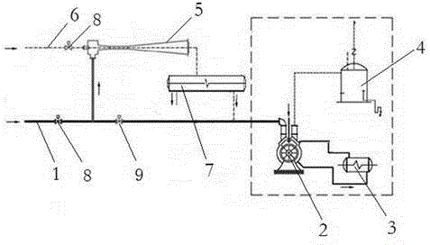
[0045] The difference between this embodiment and Embodiment 1 is that a pneumatic control valve 8 is installed at the inlet end of the condenser pipeline 1 and the power steam pipeline 6 respectively, and the condenser pipeline 1 leads to the condenser A bypass pneumatic butterfly valve 9 is installed on the rear pipe of the gas inlet 5a-2 branch. When this system is not required to work, the control room only needs to open the pneumatic butterfly valve 8 on the condenser pipeline 1 to close the power steam Pneumatic regulating valve 8 on pipeline 6, open bypass pneumatic butterfly valve 9 at the same time and get final product, this system stops working, and steam injector 5 and condenser 7 will stop working, and vacuum system will start in the working system before refitting.

Embodiment 2

[0047] The outlet pressure of the condenser 7 is designed to be 10~12kPa. Under this pressure, the vaporization temperature of the working fluid in the water ring vacuum pump 1 is about 49.5°C, which can completely solve the safety problems such as vacuum pump cavitation and rotor fracture without increasing the vacuum pump capacity. load, thereby ensuring the efficiency of the vacuum pump and maintaining the vacuum of the condenser at a high level.

Embodiment 3

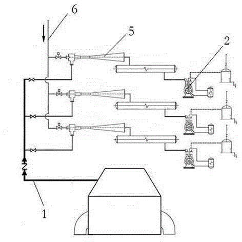
[0049] see image 3 , when the vacuum systems in the prior art are arranged in parallel to adapt to larger-scale working conditions, the steam ejectors 5 can also be connected in parallel, and each steam ejector 5 controls the number of condensers 7 connected to it respectively.


PUM


Abstract

The invention discloses a condenser steam injection vacuum system. The condenser steam injection vacuum system comprises a steam ejector and a condenser, wherein the steam ejector and the condenser are connected to a vacuum pipeline, the steam ejector comprises a head cavity and an injection pipeline, the head cavity is communicated with the injection pipeline, a power steam inlet and a condenser gas inlet are formed in the head cavity, a power nozzle which is located in the same horizontal line as the ejection pipeline is arranged on the power steam inlet, and the steam ejector takes steam as the power medium and produces a supersonic jet stream through the power nozzle to form vacuum in the head cavity so that steam and gas mixture in the condenser can be extracted. The condenser steam injection vacuum system is simple in structure, low in improvement cost and capable of enabling the vacuum of the condenser to be kept in a high-level state.

Description

technical field [0001] The invention relates to an improvement to a condenser vacuum system, in particular to a condenser steam injection vacuum system. Background technique [0002] In a thermal power plant, a water ring vacuum pump is usually used to extract the non-condensable gas in the condenser to ensure the vacuum of the condenser. The working fluid of the water ring vacuum pump is water, and its design temperature is generally 15°C. If the temperature of the working fluid is higher than its design value, the working fluid will be vaporized, which will cause cavitation of the vacuum pump, resulting in a decrease in the efficiency of the vacuum pump, resulting in The vacuum degree of the condenser decreases, which in turn reduces the power generation efficiency. [0003] In actual operation, the temperature of the working fluid will continue to rise due to the work done and the latent heat of vaporization released by the water vapor. Therefore, in order to ensure the...

Claims


Application Information

Patent Timeline
Patent Type & Authority Applications(China)
IPC IPC(8): F04F5/22F04F5/52
Inventor 程晋瑞
Owner 上海赛迩福电力技术有限公司
Why Eureka
Try Eureka