
In-situ simple shear apparatus

An in-situ, shearing device technology, applied in the direction of using a stable shear force to test the strength of materials, etc., can solve the problems of laborious use of concrete shearing devices, twisting of core samples, and inability to adjust the speed of concrete core samples. , to achieve the effect of convenient and fast detection, low cost, good promotion and application value

Active Publication Date: 2013-10-02
CABR TECH CO LTD +1
View PDF6 Cites 2 Cited by
  • Summary
  • Abstract
  • Description
  • Claims
  • Application Information

AI Technical Summary

Problems solved by technology

[0005] The purpose of the present invention is to provide an in-situ single shear instrument, to solve the problem that when the traditional concrete shearing device shears the core sample, the core sample has the danger of being twisted, and the claws in the concrete shearing device are clamped. The speed of the concrete core sample cannot be adjusted, and the technical problem that the concrete shearing device is relatively laborious to use

Method used


Image

  • In-situ simple shear apparatus
  • In-situ simple shear apparatus
  • In-situ simple shear apparatus

Examples


Embodiment Construction

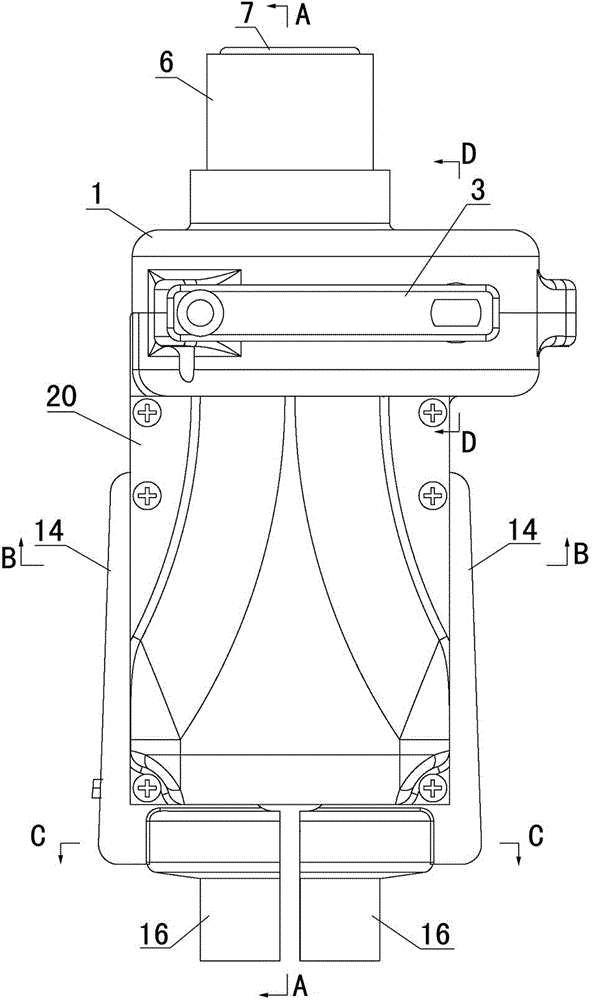
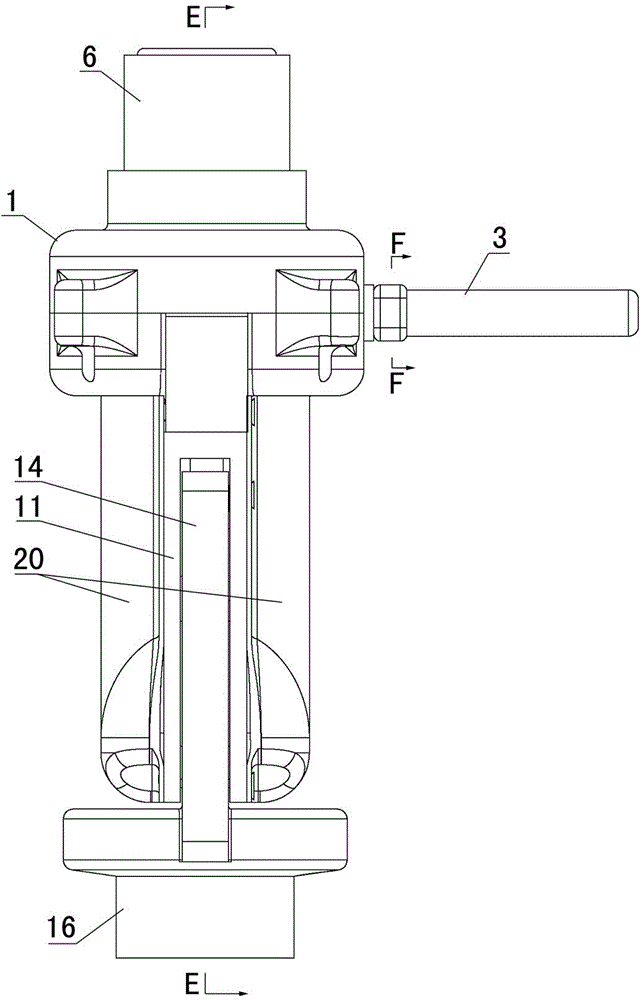
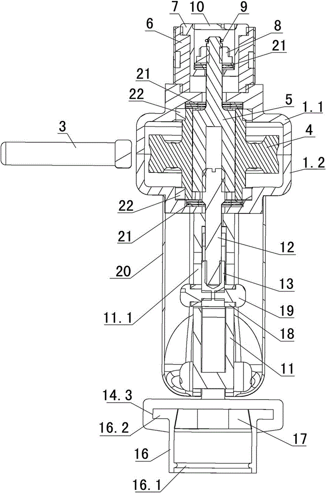
[0050] Examples see Figure 1-18 As shown, this in-situ single-shear instrument is composed of a shearing device and a data acquisition device. The shearing device includes a force application mechanism, a pressure sensing mechanism and a shearing mechanism. The data acquisition device communicates with the shearing device through a data line. The pressure sensing mechanism in the device is connected. In this embodiment, the shearing device also includes an outer shell 20 connected to the support base (see Figure 1-4 , Figure 18 ).

[0051] see Figure 1-4 , Figure 6-8 , the force applying mechanism includes a reducer housing 1, a worm 2 which is arranged in the reducer housing 1 and whose input end passes through the reducer housing to the outside of the reducer housing, and is located outside the reducer housing and is connected to the input end of the worm Drive-connected reducer handle 3 (see Figure 16 , Figure 17 ), the worm wheel 4 which is set in the reducer...


PUM


Abstract

The invention discloses an in-situ simple shear apparatus, which consists of a shearing device and a data acquisition device, wherein the shearing device comprises a stress application mechanism, a pressure sensing mechanism and a shearing mechanism; the data acquisition device is connected with the pressure sensing mechanism in the shearing device through a data line; the stress application mechanism comprises a speed reducer shell, a worm, a speed reducer handle, a worm wheel and a spline; the worm is arranged in the speed reducer shell and an input end of the worm penetrates through the speed reducer shell to the exterior of the speed reducer shell; the speed reducer handle is positioned outside the speed reducer shell and is in drive connection with the input end of the worm; the worm wheel is arranged in the speed reducer shell and is engaged with the worm; the spline is inserted in the worm wheel; the upper end face of the spline is provided with a dowel bar; and the lower end face of the spline is provided with a screw hole for being connected with the shearing mechanism. The stress application mode in the invention is the same as the lifting direction of a lifting rod, and the trend of torque is not produced to a core sample, so that the in-situ simple shear apparatus is more labor-saving to use and has a more compact and more rational structure and more attractive appearance.

Description

technical field [0001] The invention relates to the technical field of concrete strength detection, in particular to a concrete shearing device. Background technique [0002] At present, there are two commonly used concrete strength testing techniques and methods: non-destructive testing and damage testing. The non-destructive testing is divided into rebound method, comprehensive method, ultrasonic method, etc. It uses the concrete surface hardness, carbonation depth and acoustic parameters to convert the concrete strength. The non-destructive testing is easy to operate, but the test results have large errors. The damage detection is further divided into the core drilling method, the after-installation extraction method, the penetration method, etc. It uses the specified mechanical parameters of the specimen to convert the concrete strength. Many, inconvenient operation and other disadvantages, such as the commonly used core drilling method, the drilling and cutting of the ...

Claims


Application Information

Patent Timeline
IPC IPC(8): G01N3/24
Inventor 朱跃武邱平朱丽颖朱俊峰
Owner CABR TECH CO LTD
Learn More