Variable polarization panel antenna unit

A flat-panel antenna, antenna unit technology, applied in the direction of antenna, resonant antenna, antenna grounding switch structure connection, etc., can solve the problems of narrowing the frequency band, increasing the Q value of the antenna radiation, etc., and achieves the increase of the impedance allocation range and the orthogonal isolation. High, circularly polarized orthogonal isolation effect

Inactive Publication Date: 2013-10-02
AIR FORCE UNIV PLA
View PDF2 Cites 36 Cited by
  • Summary
  • Abstract
  • Description
  • Claims
  • Application Information

AI Technical Summary

Problems solved by technology

[0002] In the measures to improve the performance of flat panel antennas, various indicators often restrict each other. For example, the use of high dielectric constant dielectric substrates i

Method used


Image

  • Variable polarization panel antenna unit
  • Variable polarization panel antenna unit
  • Variable polarization panel antenna unit

Examples


Embodiment Construction

[0020] The present invention will now be described in further detail in conjunction with the accompanying drawings and preferred embodiments. These drawings are all simplified schematic diagrams, which only illustrate the basic structure of the present invention in a schematic manner, so they only show the configurations related to the present invention.

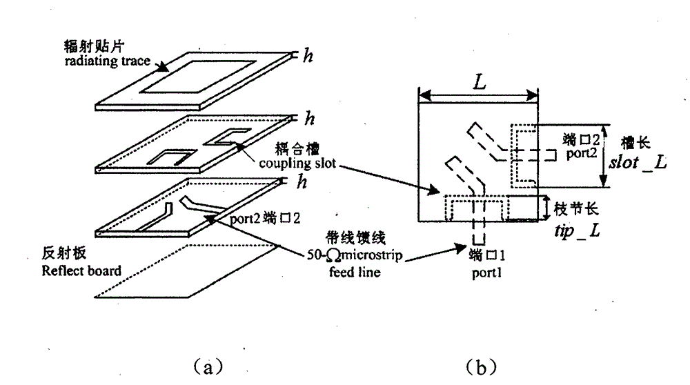
[0021] Such as figure 1 The polarization-changing flat panel antenna unit shown is composed of multi-layer metal layers coupled from top to bottom; the top metal layer from top to bottom is the radiation patch printing layer, and the surface of the printing layer is printed radiation patch; the second layer is an etching coupling groove; the third layer is a microstrip feeder network layer, on which a stripline feeder network is arranged; the fourth layer is a grounding plate, and the fourth layer and the second , Three layers constitute a stripline transmission line.

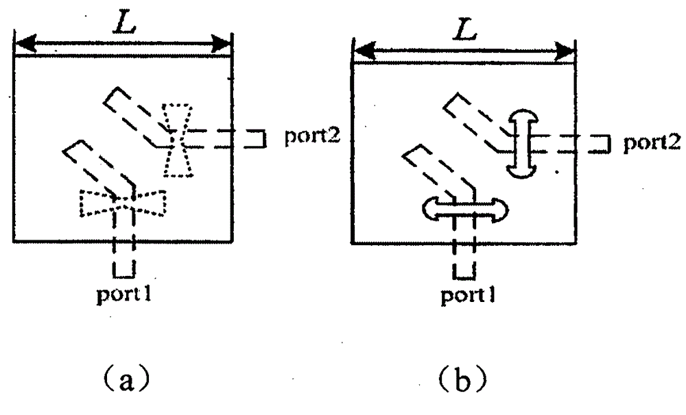
[0022] In addition to the simple rectangular slot, th...


PUM


Abstract

The invention relates to a variable polarization panel antenna unit, which is formed by slot coupling a plurality of metal layers from top to bottom; the topmost metal layer from top to bottom is a radiation patch printed layer, and the surface of the printed layer is printed with a radiation patch; the second layer is an etched coupling slot; the third layer is a microstrip line feeder network layer which is provided with a strip line feeder network thereon; and the forth layer is a grounding plate, and the forth layer and the second and third layers form a strip line transmission line. The U-shaped slot provided by the invention uses a vertical part arm length as a moderating variable, and an impedance deploying range is expanded obviously; a double-port feed structure is adopted, when the antenna works in a circular polarization mode, the TM10 and TM01 degeneracy mode field distribution has very good symmetry, and the circular polarization orthogonal isolation is high; and a strip line feed network structure is adopted, thereby not only effectively reducing spurious radiation and back reflection, but not increasing the profile thickness of the panel antenna excessively.

Description

technical field [0001] The invention relates to a flat panel antenna, in particular to a broadband, variable polarization slot coupled multilayer panel antenna. Background technique [0002] In the measures to improve the performance of flat panel antennas, various indicators often restrict each other. For example, the use of high dielectric constant dielectric substrates is one of the direct and efficient means of antenna miniaturization. However, ε r The increase of will lead to the increase of the antenna radiation Q value and the narrowing of the frequency band. Therefore, when designing an antenna, it is necessary to weigh the requirements of various indicators and carefully select the substrate material, antenna structure, patch shape, and feeding method. Contents of the invention [0003] The technical problem to be solved by the invention is to propose a novel broadband, variable polarization slot coupled multi-layer planar antenna unit. [0004] The technical so...

Claims


Application Information

Patent Timeline
IPC IPC(8): H01Q1/38H01Q1/50H01Q9/04H01Q13/08
Inventor 张厚吴文洲许冰姜聿焘许志永程智峰
Owner AIR FORCE UNIV PLA
Why Eureka
Try Eureka