
A different-frequency microstrip array and printing oscillator array common-caliber composite antenna

A technology of microstrip array and composite antenna, applied in the direction of antenna, antenna array, independent antenna unit combination, etc., can solve the problems of limited number of array elements, low radiation efficiency, low antenna radiation efficiency, etc.

Inactive Publication Date: 2013-10-02
SHANGHAI RADIO EQUIP RES INST
View PDF3 Cites 19 Cited by
  • Summary
  • Abstract
  • Description
  • Claims
  • Application Information

AI Technical Summary

Problems solved by technology

[0004] Dual-band antenna arrays can meet specific application requirements, but under the same caliber, the radiation efficiency of antennas working in low-frequency bands is lower than that of full arrays
Mainly limited by the high-frequency antenna, the low-frequency array element is suitable for placement on the common interface but has low radiation efficiency, and the number of array elements that can be placed is relatively limited.

Method used


Image

  • A different-frequency microstrip array and printing oscillator array common-caliber composite antenna
  • A different-frequency microstrip array and printing oscillator array common-caliber composite antenna
  • A different-frequency microstrip array and printing oscillator array common-caliber composite antenna

Examples


Embodiment Construction

[0027] The present invention will be further elaborated below by describing a preferred specific embodiment in detail in conjunction with the accompanying drawings.

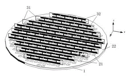
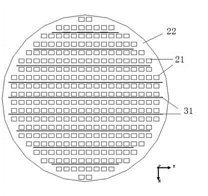
[0028] Such as figure 1 As shown, a multi-frequency microstrip array and a printed dipole array have a common aperture composite antenna, including a base 1; a microstrip array antenna, which is arranged on the surface of the base 1; The microstrip array antenna works in the Ku band (high band), and the printed dipole array antenna works in the C band (low band). The microstrip array antenna comprises microstrip patch antenna units 21 and microstrip patch antenna dielectric boards 22 distributed in uniform arrays in several rows. The microstrip patch antenna dielectric board 22 is horizontally arranged on the base 1, and the microstrip patch antenna unit 21 uniform arrays are distributed on the microstrip patch antenna dielectric board 22 (that is, the xoy plane), and the microstrip patch antenna dielectric boar...


PUM


Abstract

The invention discloses a different-frequency microstrip array and printing oscillator array common-caliber composite antenna. The different-frequency microstrip array and printing oscillator array common-caliber composite antenna comprises: a pedestal, a microstrip array antenna which is arranged on a surface of the pedestal in a plying-up mode, and a printing oscillator array antenna which is arranged on the pedestal in a vertical model. The microstrip array antenna comprises a plurality of rows of microstrip paster antenna units which are in uniformly arrayed distribution. The printing oscillator array antenna comprises a plurality of rows of printing oscillator antenna medium blocks which are parallel to each other, and a plurality of printing oscillator antenna units which are separated attached on the front surfaces and reverse surfaces of the printing oscillator antenna medium blocks. The printing oscillator antenna medium blocks are separately arranged on the pedestal in a vertical mode, and are plugged into the microstrip paster antenna units at intervals. The antenna of the invention is compact in structure. The antenna ingeniously integrates the double-surface printing oscillator antenna in a low wave band and the microstrip paster antenna in a high wave band, so that shield between the two antennas in different wave bands is reduced. The antenna is advantageous in being light in weight, high in efficiency, and in being easy to process and conform.

Description

technical field [0001] The invention relates to an antenna, in particular to a composite antenna with a common aperture of a different-frequency microstrip array and a printed vibrator array. Background technique [0002] The different-frequency common-aperture microwave system can accurately detect, intercept or track the ground or target under complex background and strong interference, and has better positioning, all-weather and anti-jamming performance than the single-sensor microwave system. A new technical way of detection and guidance. With the rapid development of science and technology, dual-band composite technology has been widely used in aerospace and other fields. [0003] As an important component of a different-frequency microwave system, the different-frequency antenna plays a key role in the performance of the system. Common-aperture multi-frequency antennas are generally composed of waveguide slot plate arrays, waveguide arrays, vibrator arrays, microstri...

Claims


Application Information

Patent Timeline
Patent Type & Authority Applications(China)
IPC IPC(8): H01Q21/00H01Q21/30H01Q1/36H01Q1/38
Inventor 王月娟李欣玄晓波张立东
Owner SHANGHAI RADIO EQUIP RES INST
Learn More