Eureka AIR delivers breakthrough ideas for toughest innovation challenges, trusted by R&D personnel around the world.

A 12/4 pole single winding bearingless switched reluctance motor and its control method

A switched reluctance motor and bearingless technology, which is applied in the direction of AC motor control, control system, synchronous machine, etc., can solve the problems of bearingless motor suspension instability, complex control algorithm, and affecting the real-time control effect of suspension force, etc., to achieve the concept Novel, simplified control algorithm, ingeniously designed effects

Active Publication Date: 2015-12-02
NANJING UNIV OF AERONAUTICS & ASTRONAUTICS
View PDF1 Cites 0 Cited by
  • Summary
  • Abstract
  • Description
  • Claims
  • Application Information

AI Technical Summary

Problems solved by technology

Due to the dual functions of rotation and suspension, the high-speed adaptability of BSRM has been further improved, and it has better application advantages in aerospace and military fields. On the basis of double-winding BSRM, two sets of windings are equivalent to one set winding and generate torque and levitation force at the same time, and develop into single-winding BSRM technology, which simplifies the motor structure and makes the control method more flexible. There is coupling
In order to improve the operating performance of the motor, the required control algorithm is quite complicated. In addition, when the motor speed rises to a certain level, due to the dual drive of the transformer potential and the motion potential, the excitation current will not decrease with the shutdown of the main switch. , the phenomenon of chopper failure occurs, which affects the real-time control effect of the suspension force, and in severe cases will lead to suspension instability of the bearingless motor

Method used


Image

  • A 12/4 pole single winding bearingless switched reluctance motor and its control method
  • A 12/4 pole single winding bearingless switched reluctance motor and its control method

Examples


Embodiment Construction

[0015] The technical scheme of the present invention is described in detail below in conjunction with accompanying drawing:

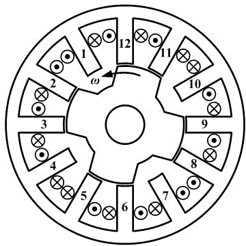
[0016] A 12 / 4 pole single winding bearingless switched reluctance motor, its structure is as follows figure 1 As shown, it consists of a stator with 12 tooth poles and a rotor with 4 tooth poles. Each pole of the stator is independently wound with a set of field windings. There is no winding on the rotor. The rotor of a 12 / 4-pole single-winding bearingless switched reluctance motor The teeth are 30° wider than the stator teeth.

[0017] The control method of the 12 / 4-pole single-winding bearingless switched reluctance motor is described as follows:

[0018] 1. The controller and current conduction mode of the stator winding: 12 sets of windings are independently controlled, and the current of each set of windings is unidirectionally conducted. The asymmetrical half-bridge circuit is selected as the circuit topology of the main winding power converter. ...


PUM


Abstract

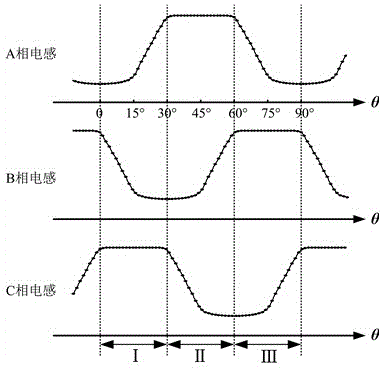
The invention discloses a 12 / 4 pole single winding bearingless switch reluctance motor and a control method thereof. The motor comprises a stator with 12 gear poles and a rotor with 4 gear poles; each pole of the stator winds a set of excitation windings; the rotor winds no winding; the rotor gear is wider than the stator gear by 30 degrees to enable each inductance to have a maximum induction flat-top area with 1 / 3 period. When the motor is in motor-driven operation, if the two phases in an inductance rising area and an inductance flat-top area are communicated simultaneously, the phase in the inductance rising area can produce a torque, and the phase in the inductance flat-top area can produce a suspension force; when the motor is in motor-driven operation, if only the phase in the inductance flat-top area is communicated, four windings of the phase are individually controlled to produce the suspension force and to provide excitation for the electricity generation stage, and later to generate electricity in an inductance drop area with follow current. The method controls the suspension force and the torque regionally, realizes the decoupling of the suspension force and the torque, simplifies the control algorithm, improves the radial bearing capacity and the high-speed adaptability of the motor, has generality and popularization in structure, and enables the field of the bearingless switch reluctance motor to gain a new development.

Description

technical field [0001] The invention relates to a 12 / 4-pole single-winding bearingless switched reluctance motor and a control method thereof, belonging to the technical field of bearingless switched reluctance motors. Background technique [0002] The switched reluctance motor has the characteristics of simple structure, reliable operation, low cost and high-speed adaptability. It has been widely used in aerospace, military, civil and other fields. It is a bearingless switched reluctance motor integrating magnetic bearing and motor functions. (hereinafter referred to as BSRM) while achieving suspension operation, the volume and weight are greatly reduced, and the power density is improved. Due to the dual functions of rotation and suspension, the high-speed adaptability of BSRM has been further improved, and it has better application advantages in aerospace and military fields. On the basis of double-winding BSRM, two sets of windings are equivalent to one set winding and ...

Claims


Application Information

Patent Timeline
Patent Type & Authority Patents(China)
IPC IPC(8): H02K19/00H02P25/08
Inventor 曹鑫邓智泉刘泽远赵贺
Owner NANJING UNIV OF AERONAUTICS & ASTRONAUTICS
Why Eureka
Eureka Blog
Learn More