Triaxial shearing and seepage integrated experimental method for hydrate-containing sediments
A hydrate-containing, triaxial shearing technique for testing material strength, permeability/surface area analysis, instrumentation, etc. using a stable shear force applied
- Summary
- Abstract
- Description
- Claims
- Application Information
AI Technical Summary
Problems solved by technology
Method used
Image
Examples
Embodiment 1
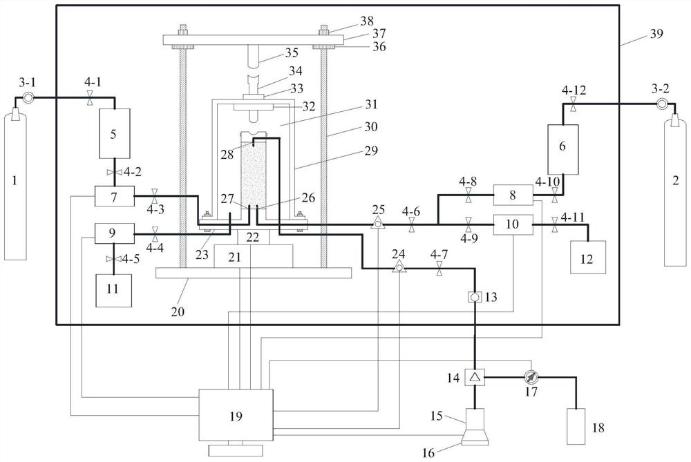
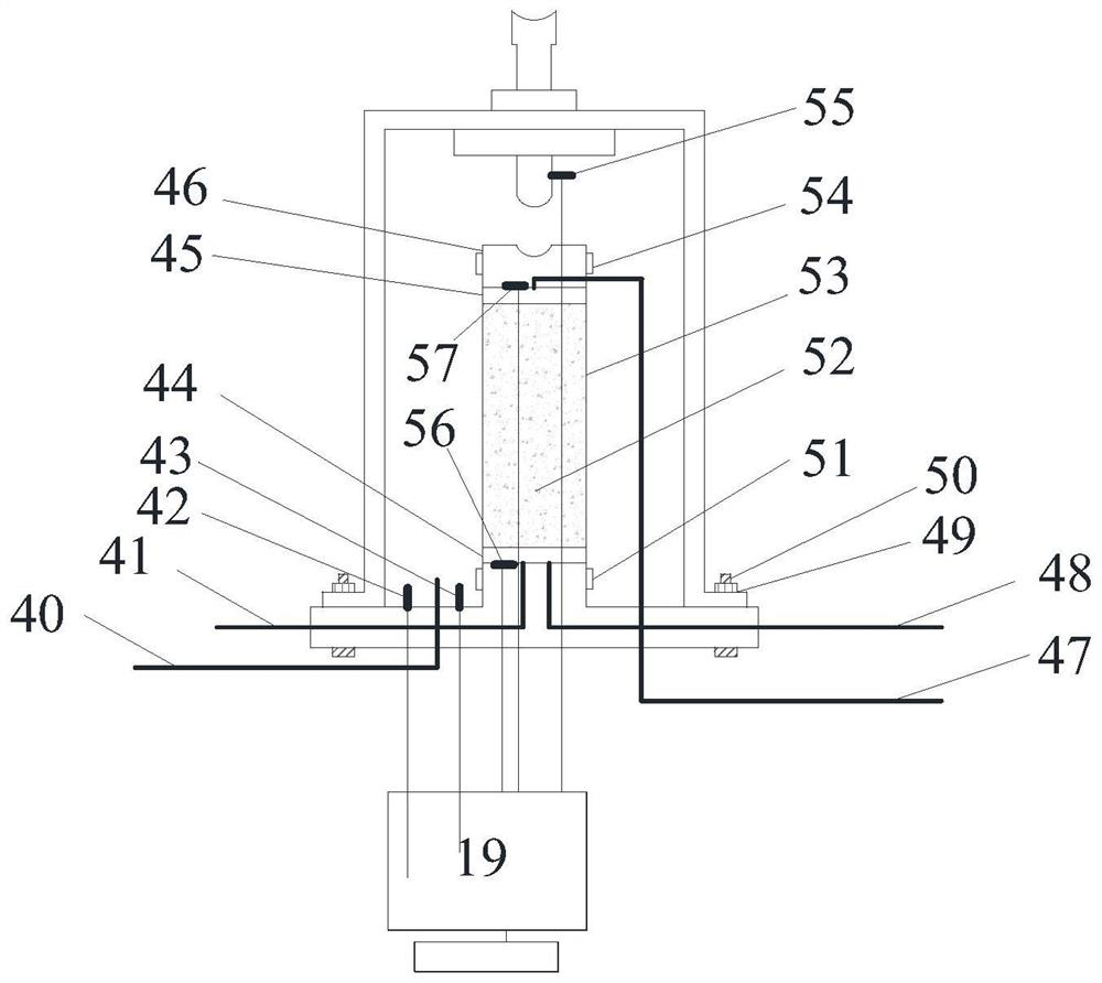
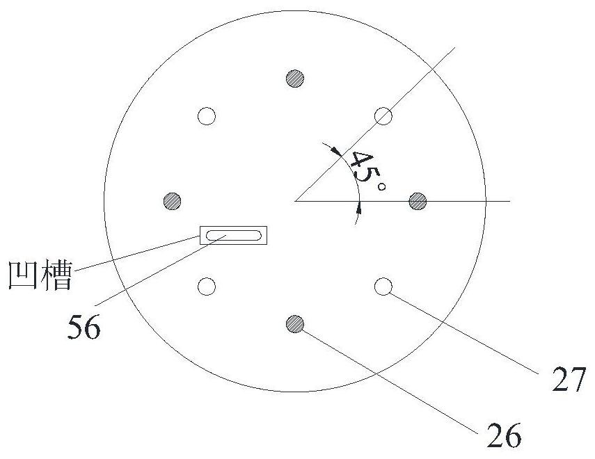
[0043] An integrated experimental setup, including a triaxial pressure chamber 31, such as figure 2 and Figure 5 As shown, outside the triaxial pressure chamber 31 is a triaxial pressure chamber cover 29, which is fixed to the sample base 23 by the triaxial instrument cover nut 49 and the triaxial instrument cover bolt 50; image 3 As shown, the sample base 23 is provided with a week of through holes, the through holes are alternately arranged sample base seepage holes 26 and sample base air inlet holes 27, the sample base seepage holes 26 are connected with the seepage inlet pipe 48, and the sample base The air inlet hole 27 of the base is connected with the pore pressure inlet pipe 41, and communicates with the sample 52 through the two through holes, and the seepage inlet pipe 48 is provided with a seepage inlet pressure sensor 25 to monitor the seepage inlet pressure; in the sample base 23 Also be provided with groove, the sample base pressure sensor 56 is installed in ...
Embodiment 2
[0061] The seepage hole 26 of the adjacent sample base and the air inlet hole 27 of the sample base are arranged at an angle of 45°; the seepage holes 28 of the adjacent sample cap are arranged at an angle of 90°. In order to ensure that the pressure difference in the seepage process is stable, the pressure difference is evenly distributed, and the permeability is good, the seepage holes 26 of the sample base, the air inlet holes 27 of the sample base and the seepage holes 28 of the sample cap in the present invention have multiple and evenly distributed, such as image 3 and Figure 4 shown; and the central angle formed between the air inlet hole 27 of the sample base and the seepage hole 26 of the sample base is 45 °, as image 3 Shown; The central angle formed between the seepage holes 28 of the sample cap is 90°.
[0062] All the other are identical with embodiment 1.
Embodiment 3
[0064] A first valve 4-1 is provided between the methane pressure regulating valve 3-1 and the methane gas storage tank 5, and a twelfth valve 4-12 is provided between the nitrogen pressure regulating valve 3-2 and the nitrogen gas storage tank 6; A second valve 4-2 is provided between the gas storage tank 5 and the pore pressure controller 7; a third valve 4-3 is provided between the pore pressure controller 7 and the air inlet 27 of the sample base; the confining pressure inlet pipe 40 is provided with a fourth valve 4-4; a fifth valve 4-5 is provided between the fuel tank 11 and the confining pressure controller 9; A sixth valve 4-6 is provided in the main pipeline after the pipeline of the controller 8 and the seepage hole 26 of the sample base is merged; a ninth valve 4-6 is provided on the sub-pipeline between the liquid seepage pressure controller 10 and the seepage hole 26 of the sample base 9. An eighth valve 4-8 is provided on the branch line between the nitrogen see...
PUM
 Abstract
Description
Claims
Application Information
 - R&D
- Intellectual Property
- Life Sciences
- Materials
- Tech Scout
- Unparalleled Data Quality
- Higher Quality Content
- 60% Fewer Hallucinations
Browse by: Latest US Patents, China's latest patents, Technical Efficacy Thesaurus, Application Domain, Technology Topic, Popular Technical Reports.
© 2025 PatSnap. All rights reserved.Legal|Privacy policy|Modern Slavery Act Transparency Statement|Sitemap|About US| Contact US: help@patsnap.com


