
Tool turret for machining workpieces and machining system with such tool turret

A technology for tool turret and workpiece processing, which is applied in metal processing machinery parts, tool holders, manufacturing tools, etc., can solve the problems of no longer being able to replace tools, different expansion characteristics, and tool turret clamping, etc., to avoid thermal stress. , high cutting speed, improved productivity and economic effects

Inactive Publication Date: 2015-12-09
5ME IP
View PDF8 Cites 0 Cited by
  • Summary
  • Abstract
  • Description
  • Claims
  • Application Information

AI Technical Summary

Problems solved by technology

A disadvantage of such tool turrets is that it is difficult to seal the connection between the conveying lines, since on the one hand the stator must be pressed against the rotor with sufficient force due to the different expansion coefficients to seal the connection, but on the other hand On the one hand, the force must not be too high, because otherwise the tool turret will be clamped and the tool can no longer be changed
This is especially problematic when cryogenic cooling media are used at different temperatures or when several different cryogenic cooling media are used due to the different expansion properties of the stator and rotor

Method used


Image

  • Tool turret for machining workpieces and machining system with such tool turret
  • Tool turret for machining workpieces and machining system with such tool turret
  • Tool turret for machining workpieces and machining system with such tool turret

Examples


Embodiment Construction

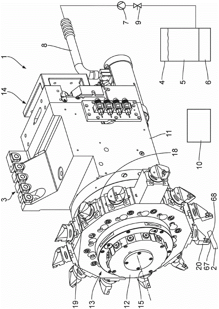
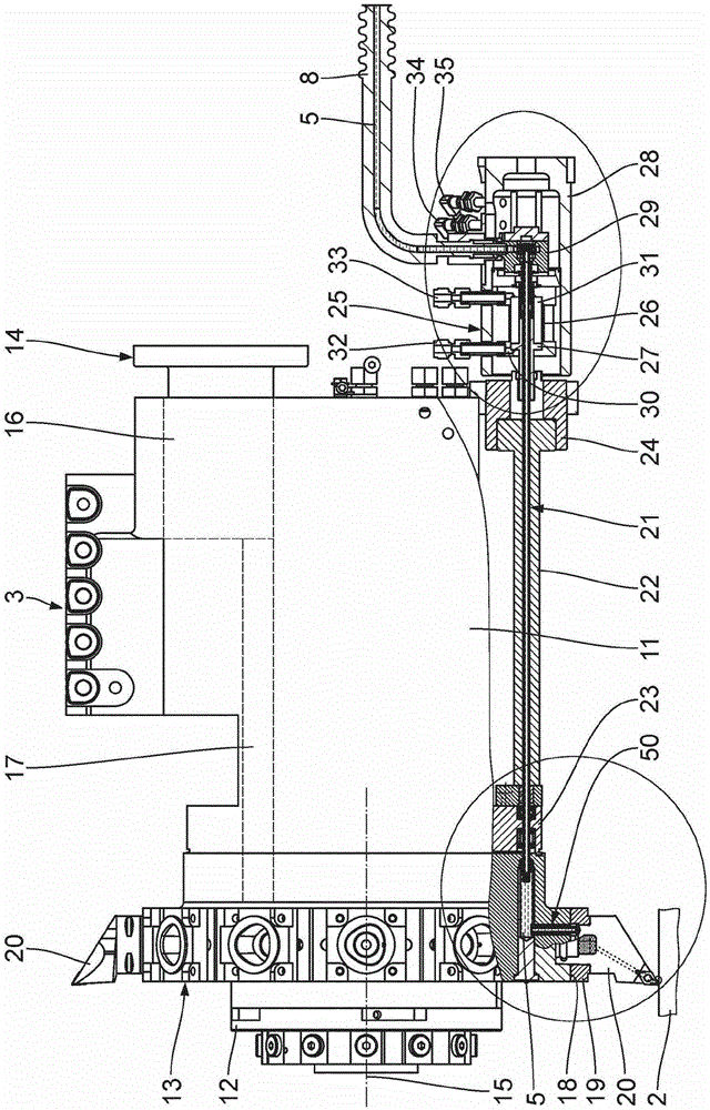
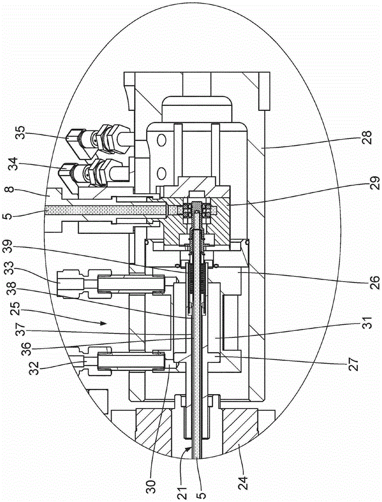
[0032] Refer below Figures 1 to 6 A first embodiment of the present invention will be described. The machine tool, not shown in detail, has a processing system 1 for cutting metal workpieces 2, which processing system includes a tool turret 3, a store 4 for providing thermal insulation of a cryogenic cooling medium 5, a cryogenic cooling medium 5 for cooling Cooler device 6 for medium 5 , delivery pump 7 , supply line 8 with associated shut-off valve 9 and control device 10 . The supply line 8 is connected to the accumulator 4 and the tool turret 3 and is thermally insulated. The tool turret 3 , the cooler device 6 , the delivery pump 7 and the shut-off valve 9 can be controlled by means of a control device 10 . Machine tool configurations other than the machining system 1 are conventional and known.

[0033] The tool turret 3 has a housing 11 in which a fixed central shaft 12 is mounted. The central shaft 12 protrudes from the housing 11 at the end and serves to support ...


PUM


Abstract

A tool turret for machining workpieces has a housing and with a part that can be rotated around an axis of rotation into several rotary positions. On the rotating part, several tool holders are mounted on the circumference for holding tools to which a cryogenic cooling medium can be fed by means of a first feed line and a respective second feed line. The first feed line can be moved in a linear manner in at least some sections by linear actuator whereby the first feed line is connected in a first position with the second feed line belonging to the tool in work position and in a second position is disconnected from the second feed lines for changing the rotary position of the rotating part. The tool turret enables the cryogenic cooling medium to be fed to the tools in a simple and reliable manner.

Description

technical field [0001] The invention relates to a tool turret for machining workpieces. Furthermore, the invention relates to a machining system with such a tool turret. The machining system is in particular part of a machine tool for machining workpieces. Background technique [0002] DE60111162T2 (corresponding to EP1208940B1) discloses a machine tool with a tool turret for cutting metal workpieces. Through the tool turret, the low-temperature cooling medium is delivered to the corresponding tool that is acting on the workpiece to be processed. To this end, the tool turret comprises a polymer rotor with a first coefficient of thermal expansion and a corresponding metal stator with a second coefficient of thermal expansion. Extending through the stator is a first conveying line having a first line section extending concentrically to the rotor axis of rotation and a second line section extending radially relative to the axis of rotation. In the working position of the re...

Claims


Application Information

Patent Timeline
Patent Type & Authority Patents(China)
IPC IPC(8): B23Q11/10
CPCB23Q11/1053B23B29/323B23Q2220/002Y10S29/05Y10S29/092Y10S82/90Y10T29/5154Y10T29/5155Y10T82/2587B23Q5/04B23Q11/103B23Q39/00B23Q2039/004
Inventor M·I·梅达尔H·朗W·霍恩W·豪斯
Owner 5ME IP
Learn More