Eureka AIR delivers breakthrough ideas for toughest innovation challenges, trusted by R&D personnel around the world.

Ultra-clean discharge integrating system and synergic removal method of circulating fluidized bed boiler

A collaborative removal method and circulating fluidized bed technology, applied in fluidized bed combustion equipment, chemical instruments and methods, combustion methods, etc., can solve problems such as environmental pollution, ammonia escape, and large footprint

Pending Publication Date: 2020-10-30
哈尔滨红光锅炉总厂有限责任公司
View PDF2 Cites 0 Cited by
  • Summary
  • Abstract
  • Description
  • Claims
  • Application Information

AI Technical Summary

Problems solved by technology

[0003] The invention aims to solve the problems of large investment cost, high operating cost and large occupied area of ​​equipment such as wet desulfurization, SCR denitrification, electric bag or wet electrostatic precipitator system in the existing circulating fluidized bed boiler combustion pollutant treatment system. , will also cause environmental pollution such as equipment corrosion, wastewater discharge, ammonia escape, colored plume, gypsum rain, smog, etc., and then provide a circulating fluidized bed boiler ultra-clean emission integrated system and collaborative removal method

Method used


Image

  • Ultra-clean discharge integrating system and synergic removal method of circulating fluidized bed boiler
  • Ultra-clean discharge integrating system and synergic removal method of circulating fluidized bed boiler
  • Ultra-clean discharge integrating system and synergic removal method of circulating fluidized bed boiler

Examples


Embodiment Construction

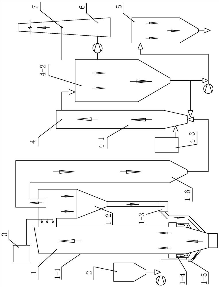
[0023] see Figure 1-Figure 3 As shown, the circulating fluidized bed boiler ultra-clean emission integrated system of this embodiment includes a low-emission circulating fluidized bed boiler 1, a limestone desulfurization device 2, a denitrification device 3 and a humidification activation removal device 4; a low-emission type The top of the furnace 1-1 of the circulating fluidized bed boiler 1 communicates with the separator 1-2, the lower part of the separator 1-2 communicates with the upper part of the feeder 1-3, and the feeder 1-3 communicates with the low-emission circulating flow The bottom of the furnace 1-1 of the bed boiler 1 is connected, the denitrification device 3 is connected with the separator 1-2, and the furnace 1-1 is connected with the limestone desulfurization device 2;

[0024] The humidification activation removal device 4 includes a humidification activation tower 4-1, a dust removal device 4-2 and a humidifier 4-3; a tail flue 1-6, a dust removal devi...


PUM

PropertyMeasurementUnit
Granularityaaaaaaaaaa

Abstract

The invention relates to an ultra-clean discharge integrating system and synergic removal method of a circulating fluidized bed boiler. The integrating system comprises a low discharge circulating fluidized bed, a limestone desulfurizing device, a backup denitration device and a humidifying and activating removal device, wherein the humidifying and activating removal device comprises a humidifyingand activating tower, a dedusting device and a humidifier; a tail flue, the dedusting device and the humidifier communicate to the humidifying and activating tower, separately. The ultra-clean discharge synergic removal method comprises the following steps of I, feeding limestones with certain granularity from the limestone desulfurizing device into a hearth to be desulfurized in the hearth; II,feeding a fuel into the hearth for low nitrogen combustion through a coal feeding device; III, feeding flue gas from the tail flue into the humidifying and activating tower of the humidifying and activating removal device, wherein the humidifier sprays water to the humidifying and activating tower to humidify, dedust, activate and desulfurize; and IV, detecting purified flue gas and discharging the flue gas by reaching the standard. The system and method can achieve ultra-clean discharge of SO2, NOx and PM and remove SO3, heavy metal Hg and the like synergically efficiently. No waste water isdischarged and anticorrosion treatment is not needed by the flue and a chimney.

Description

technical field [0001] The invention relates to a circulating fluidized bed boiler and a discharge system, in particular to a circulating fluidized bed boiler ultra-clean discharge integrated system and a coordinated removal method. Background technique [0002] The combustion technology of circulating fluidized bed boilers has developed rapidly due to its environmental protection and energy saving performance. With the implementation of the new boiler air pollutant ultra-clean emission standards, the development of circulating fluidized bed boiler combustion coordinated control and auxiliary system integration ultra-clean emission technology has been accelerated. Development and application, so as to achieve ultra-clean emissions, high-efficiency combustion and safe operation. The existing circulating fluidized bed boiler needs to arrange a variety of environmental protection treatment devices in the treatment system outside the furnace to solve the problem that the initial...

Claims


Application Information

Patent Timeline
IPC IPC(8): F23C10/26F23C10/20F23C10/28F23N3/00F23J15/04F23J15/02B01D53/50B01D53/83B01D53/60B01D53/64B01D53/75B01D50/00
CPCF23C10/26F23C10/20F23C10/28F23N3/00F23J15/04F23J15/022B01D53/508B01D53/83B01D53/75B01D53/60B01D53/64B01D2251/404B01D2251/602B01D2257/602B01D2258/0283B01D50/60Y02A50/20
Inventor 张福强
Owner 哈尔滨红光锅炉总厂有限责任公司
Why Eureka
Eureka Blog
Learn More