foam dispenser

An ejector and foam technology, applied in the direction of ejection device, liquid ejection device, closing, etc., can solve the problems of limited liquid passage size, increased manufacturing cost, large ejection head, etc., to prevent bad situations and reduce the use of materials. Effect

Active Publication Date: 2015-08-05
YOSHINO KOGYOSHO CO LTD
View PDF6 Cites 0 Cited by
  • Summary
  • Abstract
  • Description
  • Claims
  • Application Information

AI Technical Summary

Problems solved by technology

[0007] As a result, the size of the liquid passage is easily limited, and if a large discharge port or a discharge passage is required, the discharge head itself must be made very large, and there is a concern that the manufacturing cost will increase.

Method used


Image

  • foam dispenser
  • foam dispenser
  • foam dispenser

Examples


Embodiment Construction

[0028] Hereinafter, embodiments of the present invention will be described with reference to the drawings.

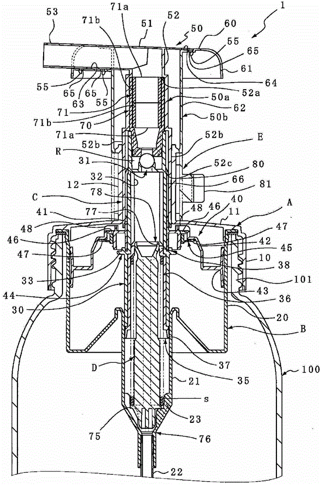
[0029] figure 1 as well as figure 2 It is a figure which shows an example of the foam dispenser 1, and the foam dispenser 1 is provided with the mounting cap A, the cylinder member B, the operation member C, the poppet valve body D, and the spacer E.

[0030] The mounting cap A is a component for fixing the foam sprayer 1 to the container body 100, and the mounting cap A is extended from the upper end edge of the peripheral wall 10 of the outer periphery of the mouth and neck portion 101 of the container body 100, and is set at the center. The top wall 11 of the window hole through which the operating member C penetrates, and a guide cylinder 12 is provided standing upward from the periphery of the window hole.

[0031] In the cylinder member B, a small-diameter liquid cylinder 21 is concentrically extended below a large-diameter air cylinder 20 whose upper end is fi...


PUM


Abstract

Provided is a foam dispenser in which upward and downward displacement of an actuator causes a content liquid within a liquid cylinder (21) and air within an air cylinder (20) to be mixed and foamed, such that the foam so generated is dispensed from an outlet of a dispenser head (50). The dispenser head (50) has a structure with a minimized thickness to thereby increase the dispensing amount. The dispenser head (50) includes two members, i.e., a first member (50a) and a second member (50b), that have special configuration for allowing the two members (50a, 50b) to be easily removed from a die and formed in a small thickness.

Description

technical field [0001] The present invention relates to foam dispensers. Background technique [0002] As foam ejectors, there have been proposed various ejectors (for example, refer to Patent Document 1) in which the upper half is formed as a large-diameter cylinder and the lower half is formed as a small-diameter cylinder. (Cylinder) part hangs down in the container body, and from the cylinder part, the liquid in the small-diameter cylinder and the air in the large-diameter cylinder are pressed by the action part standing up under the state of applying force from above. The foamed part fitted in the operating part passes through and foams, and is discharged from the nozzle. [0003] In the manufacture of conventional foam dispensers, the main problem is simplification of the mold structure during molding. As a result, for example, the discharge head constituting the upper end of the operating part is formed as a single part and has a thick wall. [0004] prior art litera...

Claims


Application Information

Patent Timeline
Patent Type & Authority Patents(China)
IPC IPC(8): B65D47/34B05B11/00B65D83/76
CPCB05B11/3087B05B11/0005B05B11/3069B05B11/3004B05B7/0025B05B11/0089B05B7/0037B05B11/1004B05B11/1069B05B11/1047B05B11/1087B65D47/00B05B11/00B65D83/00
Inventor 水岛博
Owner YOSHINO KOGYOSHO CO LTD
Why Eureka
Try Eureka