Control devices for internal combustion engines
A technology for control devices and internal combustion engines, which is applied in engine control, electrical control, exhaust devices, etc., and can solve problems such as decreased detection accuracy and difficult particulate filter fault diagnosis
- Summary
- Abstract
- Description
- Claims
- Application Information
AI Technical Summary
Problems solved by technology
Method used
Image

Examples
Embodiment approach 1
[0048] Structure of Embodiment 1
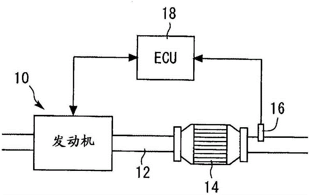
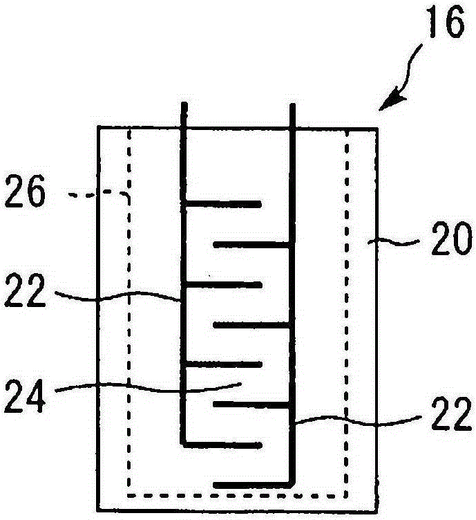
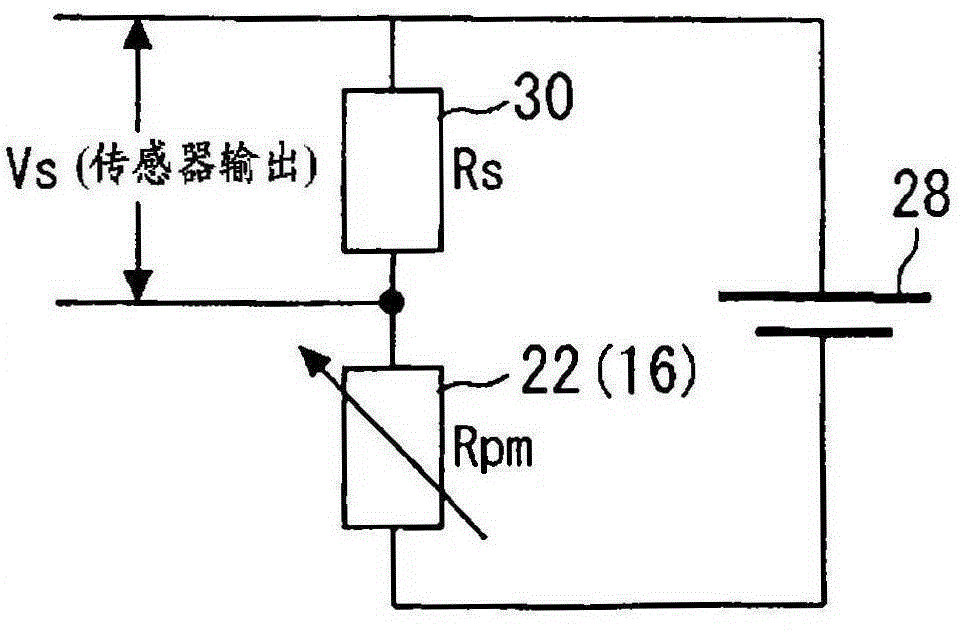
[0049] Below, refer to figure 1 and Figure 6 Embodiment 1 of the present invention will be described. figure 1It is an overall configuration diagram for explaining the system configuration of Embodiment 1 of the present invention. The system of the present embodiment has an engine 10 as an internal combustion engine, and a particulate filter 14 for trapping PM in exhaust gas is provided in an exhaust passage 12 of the engine 10 . The particulate filter 14 is constituted by a known filter including, for example, a DPF (Diesel Particulate Filter, Diesel Particulate Filter). In addition, a resistive PM sensor 16 for detecting the amount of PM in the exhaust gas is provided on the downstream side of the particulate filter 14 in the exhaust passage 12 . The PM sensor 16 is connected to an ECU (Electronic Control Unit, electronic control unit) 18 that controls the operating state of the engine 10 . The ECU 18 is composed of an arithmetic proc...
Embodiment approach 2
[0072] Next, refer to Figure 7 ~ Figure 9 Embodiment 2 of the present invention will be described. The present embodiment is characterized in that zero-point abnormality determination control is executed in the same configuration and control as in the first embodiment described above. In addition, in this embodiment, the same reference numerals as in Embodiment 1 are assigned to the same components as in Embodiment 1, and description thereof will be omitted.
[0073] Features of Embodiment 2
[0074] In the present embodiment, the zero-point abnormality determination control is executed using the zero-point output Ve acquired by the zero-point correction control. In this control, it is determined that the PM sensor 16 has failed when the zero output Ve is outside a predetermined range (hereinafter referred to as a zero allowable range). The zero allowable range is set in advance according to design specifications of the sensor and detection circuit, and the like. Figure 7 I...
Embodiment approach 3
[0085] Next, refer to Figure 10 ~ Figure 12 Embodiment 3 of the present invention will be described. The present embodiment is characterized in that, in addition to the same configuration and control as in the first embodiment described above, sensitivity correction control is executed. In addition, in this embodiment, the same reference numerals as in Embodiment 1 are assigned to the same components as in Embodiment 1, and description thereof will be omitted.
[0086] Features of Embodiment 3
[0087] In the present embodiment, sensitivity correction control for correcting variations in sensor output sensitivity is executed by PM combustion control. Figure 10 It is an explanatory diagram for explaining the content of the sensitivity correction control in Embodiment 3 of the present invention. As shown in the figure, when the PM sensor is operating, the amount of captured PM increases with the passage of time, and the sensor output also increases accordingly. Then, when ...
PUM
 Abstract
Description
Claims
Application Information
 - R&D Engineer
- R&D Manager
- IP Professional
- Industry Leading Data Capabilities
- Powerful AI technology
- Patent DNA Extraction
Browse by: Latest US Patents, China's latest patents, Technical Efficacy Thesaurus, Application Domain, Technology Topic.
© 2024 PatSnap. All rights reserved.Legal|Privacy policy|Modern Slavery Act Transparency Statement|Sitemap