Rotary type grain separating device

A rotary, grain-based technology, applied in the direction of solid separation, separating solids from solids with airflow, chemical instruments and methods, etc., can solve the problems of reducing production, crushing materials, affecting the effect of impurity removal, etc., and achieves a simple overall structure , Slow down the falling speed and take up less space

Active Publication Date: 2013-10-09
山东聚阳智能装备有限公司
View PDF10 Cites 10 Cited by
  • Summary
  • Abstract
  • Description
  • Claims
  • Application Information

AI Technical Summary

Problems solved by technology

The advantage of this air separator for light miscellaneous grains is that it slows down the impact force when the materials fall, and improves the removal effect of light miscellaneous materials. The disadvantage is that there is no channel for separating the materials in the equalizing tray, and the materials tend to accumulate more in one direction. , affecting the effect of removing impurities in this direction; the impact of the materials thrown out by the equalizing plate and the grain miscellaneous separating cylinder is likely to cause the crushing of the materials and reduce the output; It needs to enter the settling chamber for settling, and the treatment effect for ultra-light impurities is not good

Method used


Image

  • Rotary type grain separating device
  • Rotary type grain separating device
  • Rotary type grain separating device

Examples


Embodiment 1

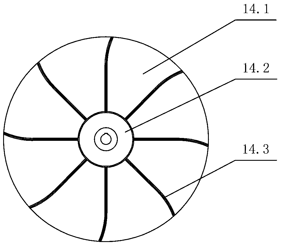
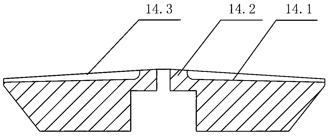
[0035] Examples of the present invention Figure 1~4 and Figure 6 , Figure 7 As shown, it includes a housing 3, a rotating disk 14, and a feeding pipe 8. The rotating disk 14 is arranged in the housing 3, and the feeding pipe 8 is fixed on the housing 3. The feeding pipe includes an oblique end of 45 and a vertical The oblique end is that the grain can flow into the housing by itself. The outlet of the feeding pipe is set directly above the rotating disk 14. The middle part of the rotating disk 14 is higher than the edge. The rotating disk 14 is an upwardly inclined curve from the edge to the middle, and the middle is A circular protrusion 14.2, fan blade 14.3 is arranged on the rotating disk 14, and the fan blade 14.3 is distributed on the disk surface 14.1 of the rotating disk 14 in a divergent shape, the circular protrusion 14.2 is fixedly connected with one end of the fan blade 14.3, and the other end of the fan blade 14.3 Extending to the edge of the rotating disk 14,...

Embodiment 2

[0042] This example Figure 5 As shown, the second collecting hopper 17 is connected to the casing 3 through four symmetrically arranged strip plates 28, so that the external natural wind can smoothly enter the casing.

Embodiment 3

[0044] This example Figure 8 As shown, one end of the adapter 4 is hinged with the middle rod, and the other end is provided with a blind hole for the insertion of the adjusting connecting rod 27. There is a side hole on the side of the blind hole, and a bolt is screwed into the side hole, and the bolt is connected to the insertion end of the adjusting connecting rod. A retaining ring is arranged between, and the retaining ring is stuck in the groove of the insertion end of the adjusting connecting rod 27. The adjusting connecting rod 27 and the adapter 4 are axially fixed and clamped by the retaining ring, and the adjusting connecting rod 27 can rotate around the axis at the same time.

[0045] work process:

[0046] When working, the motor 20 drives the rotating disk 14 to rotate, and the grain enters the rotating disk 14 through the feeding pipe 8, and is evenly distributed to the winnowing area under the drive of the rotating disk 14. 17. The joint of the shell 3 and th...


PUM


Abstract

The invention relates to a grain separating device, in particular to a grain winnowing separating device and belongs to the field of grain machinery. The rotary type grain separating device comprises a shell body, a rotary disc and a discharging tube. The rotary disc is arranged in the shell body; the discharging tube is arranged above the rotary disc; a motor is connected with the axial position of the rotary disc; a material collecting structure is arranged above the rotary disc; a winnowing region is formed among the rotary disc, the shell body and the material collecting structure; the opening portion of the shell body is connected with a wind power device. The rotary type grain separating device is reasonable in structure, small in size and occupied space, convenient to transport and suitable for application of a peasant household and small-sized operation. Grain is evenly distributed in the winnowing region, the residence time of the grain in the winnowing region is improved, the impurity removing efficiency is greatly improved, and the impurity removing efficiency is improved to 85% from 70%.

Description

technical field [0001] The invention relates to a grain sorting device, in particular to a grain winnowing sorting device, which belongs to the field of grain machinery. Background technique [0002] At present, the degree of mechanization of grain procurement in domestic grassroots grain depots is low, and a lot of grain removal is still done manually, resulting in low warehousing efficiency and high labor intensity. However, the existing equipment for cleaning light and small impurities mainly includes wind selection and screening. Wind selection uses the difference in suspension speed between materials and impurities to remove impurities with the help of wind power. At present, most wind separation cleaning equipment is bulky. The equipment is bulky and inconvenient to transport, so it is not suitable for farmers or small grain stations. When large-scale winnowing and cleaning equipment removes impurities, there are disadvantages that the grain is fed too quickly so that...

Claims


Application Information

Patent Timeline
Patent Type & Authority Applications(China)
IPC IPC(8): B07B7/00B07B11/00B07B11/06B07B11/02
Inventor 史希水于效林张德喜
Owner 山东聚阳智能装备有限公司
Why Eureka
Try Eureka