Casting type 3D printer

A 3D printer and 3D technology, applied in the field of 3D printers, can solve the problems of slow processing speed and narrow application range, and achieve the effect of fast printing speed and wide application range

Inactive Publication Date: 2013-10-09
中山科普斯特电源技术有限公司
View PDF4 Cites 23 Cited by
  • Summary
  • Abstract
  • Description
  • Claims
  • Application Information

AI Technical Summary

Problems solved by technology

[0005] The purpose of the embodiment of the present invention is to provide a casting type 3D printer, which aims to solve the problems of slow processing speed and narrow application range in the existing technical solutions

Method used


Image

  • Casting type 3D printer
  • Casting type 3D printer
  • Casting type 3D printer

Examples


Embodiment 1

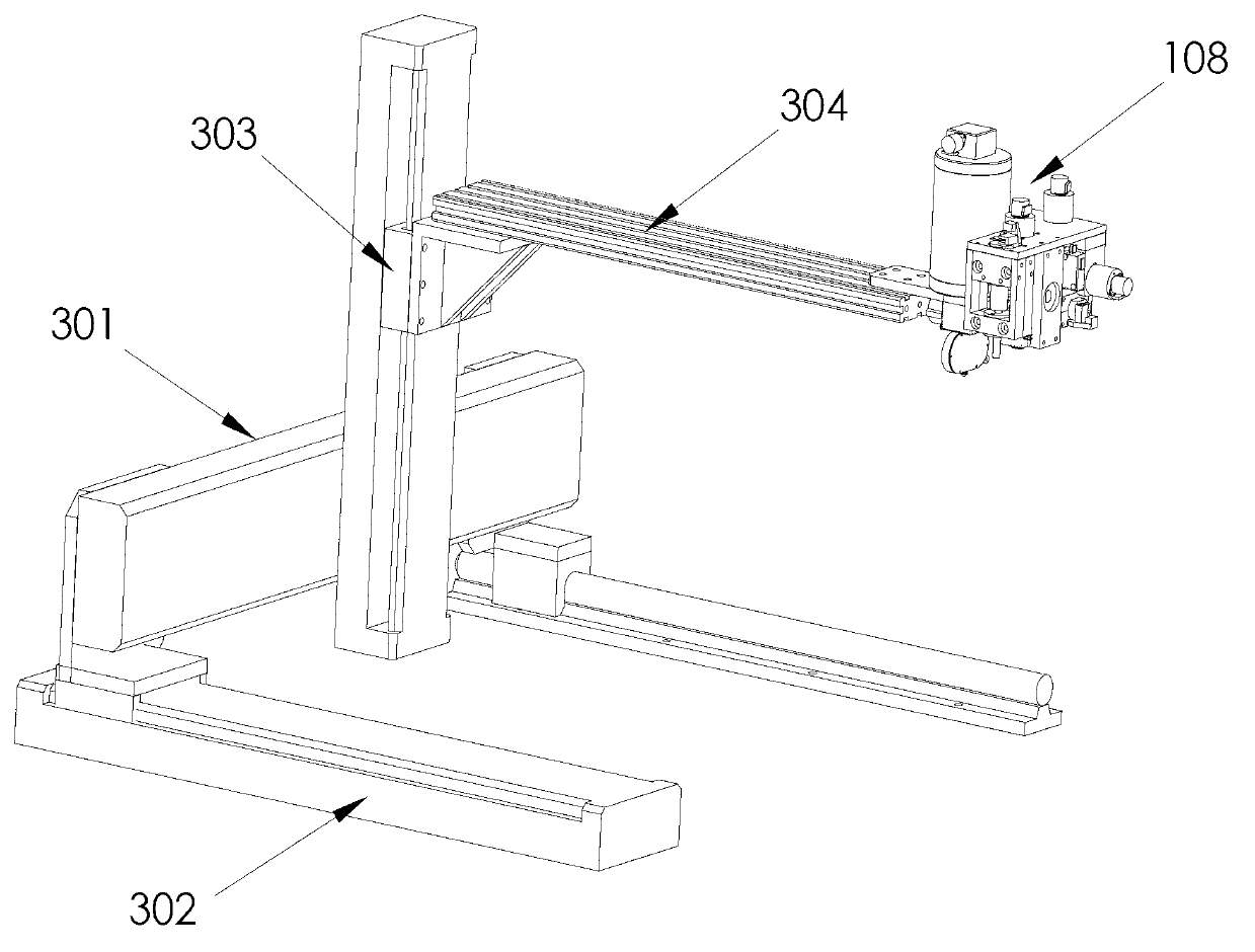
[0029] This embodiment provides a casting type 3D printer, the casting type 3D printer such as image 3 , Figure 4 shown, where, image 3 It is a three-axis linkage 3D printer, Figure 4 It is the Z-axis control in the vertical direction + the polar coordinate control in the plane. like image 3 As shown, the 3D transmission mechanism of the casting 3D printer includes: an X-axis transmission mechanism 301, a Y-axis transmission mechanism 302, a Z-axis transmission mechanism 303 and a Z-axis extension rod 304;

[0030] The X-axis transmission mechanism 301 is fixed on the Y-axis transmission mechanism 302, and the X-axis transmission mechanism 301 can move along the Y-axis direction on the Y-axis transmission mechanism 302;

[0031] The Z-axis transmission mechanism 303 is fixed on the X-axis transmission mechanism, and the Z-axis transmission mechanism 303 can move along the X-axis direction on the X-axis transmission mechanism 301;

[0032] One end of the Z-axis extens...

Embodiment 2

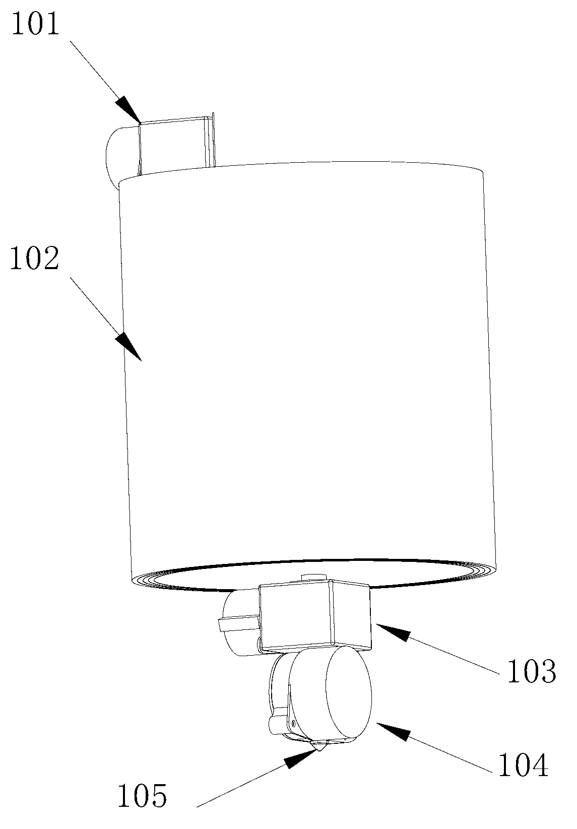
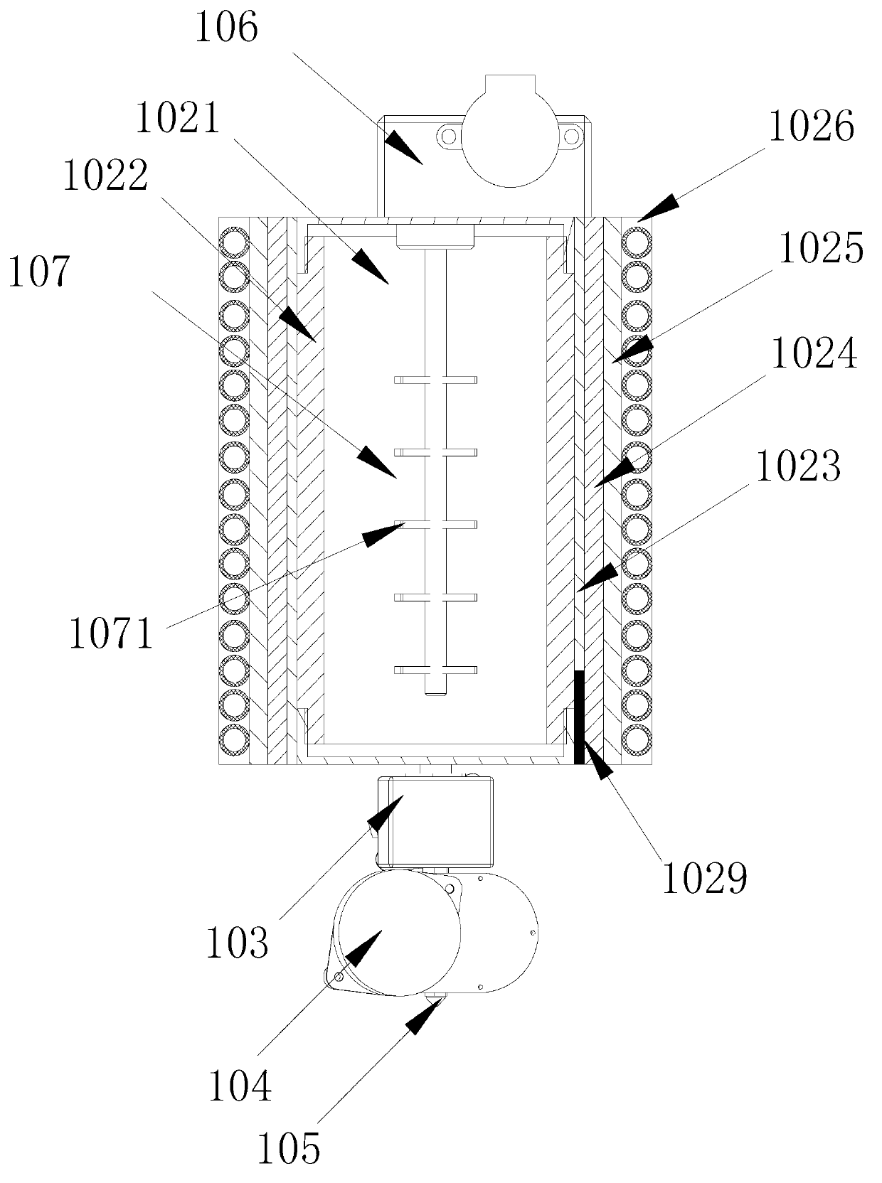
[0047] This embodiment provides a plastic melting furnace, the plastic melting furnace such as figure 2 As shown, it includes: a feeding device 101, a furnace body 102, an electric valve 103, a quantitative output pump 104 and a nozzle 105;

[0048]The furnace body 102 is, from inside to outside, a cavity 1021, a main body layer 1022, an insulating and heat-conducting layer 1023, a heating layer 1024, and an insulating and heat-insulating layer 1025; the cavity 1021 may specifically be a space for storing raw materials.

[0049] The insulating layer 1025 is used to prevent the heating layer from being directly exposed in the air, which will cause some heat to be dissipated into the air. In addition, the heating layer exposed in the air may also easily burn the user. The purpose of insulation is to prevent leakage.

[0050] The feeding device 101 is arranged on the top of the furnace body 102, and the feeding device 101 communicates with the cavity 1021;

[0051] The electri...

Embodiment 3

[0058] This embodiment provides the printing method of the casting type 3D printer shown in the first embodiment. The method includes: first, after the system of the 3D printer is powered on, according to the position of the limit switch, the entire system is returned to the origin position of the system control. Secondly, the system controls the metal or plastic melting furnace according to the materials used, and when it meets the working requirements, it enters the printing state. Then, the system inputs the outline of the 3D graphics to be printed, and prints the outline of one layer of the 3D graphics with a relatively small flow. Within the range enclosed by the outline of the layer, the system pours the entire layer with a large flow rate, and the entire layer of the 3D part is poured. After the pouring of one layer is completed, the system controls the temperature of the upper surface of the layer to a temperature suitable for secondary processing through thermal field...


PUM


Abstract

The invention relates to the field of a 3D printer, and provides the casting type 3D printer. The 3D printer comprises a 3D transmission mechanism, a Z-axis platform and a controller. The Z-axis platform is fixed on the end portion of the 3D transmission mechanism and comprises a metal or plastic smelting furnace. The metal or plastic smelting furnace comprises a feed device, a furnace body, an electric valve, a quantitative output pump and a nozzle, wherein the furnace body is used for smelting printing supplies of the 3D printer, and the controller is used for controlling the transmission of the 3D transmission mechanism, the temperature of a heating layer and the flow of the quantitative output pump. According to the technical scheme, the casting type 3D printer has the advantage of being high in printing speed.

Description

technical field [0001] The invention belongs to the field of 3D printers, and in particular relates to a casting type 3D printer. Background technique [0002] 3D printing is a new type of processing technology that has developed rapidly today, especially suitable for various personalized processing and single-piece small batch processing. 3D printing technology is generally realized by the principle of layered printing, that is, the 3D model to be printed is decomposed into sheets, and by controlling the plane positioning system, one sheet is printed at a time, and then the height is raised by one step, and the next sheet is printed. Flakes, eventually forming a full 3D shape. [0003] Common 3D printing technologies include the following: laser sintering, laser photosensitive technology, fuse manufacturing, etc. The 3D printing technology of laser sintering is to melt and shape the powder metallurgy material through high-speed heating of the laser, and the laser photosen...

Claims


Application Information

Patent Timeline
Patent Type & Authority Applications(China)
IPC IPC(8): B22F3/115B29C67/00
Inventor 王奉瑾
Owner 中山科普斯特电源技术有限公司
Why Eureka
Try Eureka