Photocuring 3D printing system and printing method

A 3D printing and light curing technology, applied in the field of 3D printing, can solve the problems of affecting the accuracy of the layer thickness of the three-dimensional model, affecting the printing speed, etc., to improve the light curing speed and printing speed, improve the printing accuracy, and improve the printing speed. Effect

Active Publication Date: 2020-03-24
YUANZHI TECH SHANGHAI CO LTD
View PDF11 Cites 8 Cited by
  • Summary
  • Abstract
  • Description
  • Claims
  • Application Information

AI Technical Summary

Problems solved by technology

[0003] Since the paving and light curing are carried out in time, the printing speed is affected. In addition, the paste-like photosensitive printing materials, such as photosensitive resin or photosensitive resin and other powder materials formed viscous award-winning printing materials, the thickness of the laying is easy to be scratched. Board gap, scraper moving speed, temperature or vibration of material carrier (printing platform), viscosity and surface characteristics of printing material, or printing material composition formula, pressure of slurry printing material and other factors, which in turn affect laying Accuracy of layer thickness and accuracy of 3D model

Method used


Image

  • Photocuring 3D printing system and printing method
  • Photocuring 3D printing system and printing method
  • Photocuring 3D printing system and printing method

Examples


Embodiment 1

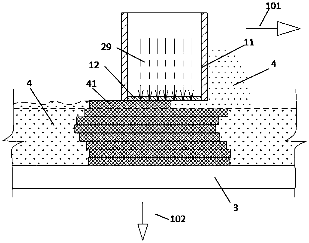
[0046] Such as figure 1 A light-curing 3D printing system shown includes a material carrier 3 and a material spreader 11 . Wherein, the spreader 11 is a scraper structure, at least part of the area on the spreader side of the spreader 11 is a light-transmitting area 12, and the light-transmitting area 12 can pass through light beams (or electromagnetic waves). The opposite side of the material container 11 and the material carrier 3, that is figure 1 The bottom of spreader 11 is shown. The light-transmitting area 12 can be realized by a light-transmitting plate, and the light beam 29 can pass through the light-transmitting area 12 to irradiate the photosensitive printing material 4 between the light-transmitting area 12 and the material carrier 3 . The spreader 11 may have a hollow structure, for example, the light-transmitting area 12 is disposed at the bottom of the hollow structure.

[0047] When printing, the driver ( figure 1 not shown in ) to drive the spreader 11 an...

Embodiment 2

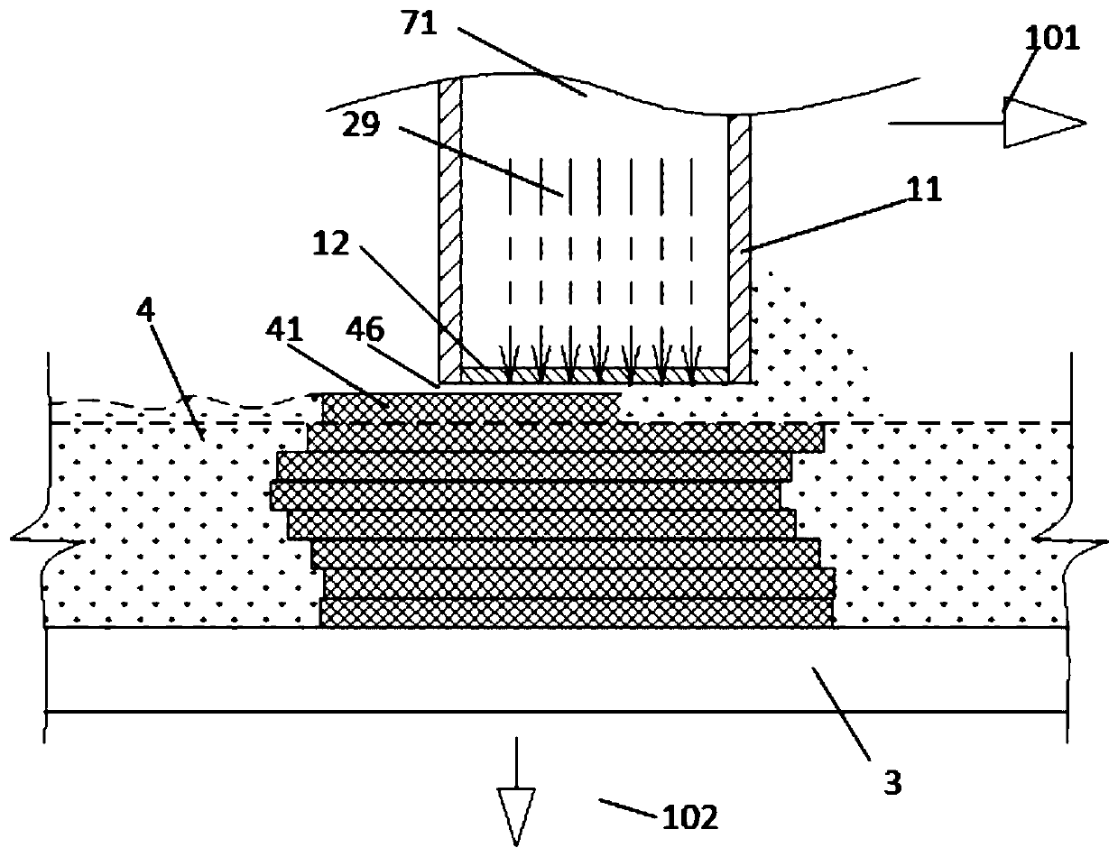
[0050] figure 2 Shown is a schematic structural diagram of Embodiment 2, which is different from Embodiment 1 in that a layer of isolation layer 46 is provided between the spreader 11 and the photosensitive printing material 4 to reduce the solidified layer 41 and the light-transmitting region 12. adhesion, the isolation layer 46 is in contact with the light-transmitting region 12 . The isolation layer 46 can be realized in various ways. For example, the light-transmitting region 12 of the spreader 11 can adopt a semi-permeable film, which can allow the light-curing inhibitor 71 (such as oxygen) with a certain pressure above to pass through the light-transmitting region 12. The pavement layer forms a photopolymerization dead zone, and the photopolymerization dead zone is in contact with the light-transmitting zone 12 . In the photopolymerization dead zone, the photosensitive printing material 4 will not be cured when the light beam 29 is irradiated, so that when the spreader...

Embodiment 3

[0054] Figure 4 It is shown that the spreader 11 can be a closed structure, and a photocuring inhibitor 71 with a preset pressure, such as oxygen, can be set inside the light-transmitting area 12 on the side facing the material carrier 3 (as shown in the bottom). The transparent semi-permeable membrane can allow oxygen to pass through, and the top adopts a transparent plate 12a. The light beam 29 emitted by the light source 2 selectively illuminates the photosensitive printing material 4 between the spreader 11 and the material carrier 3 through the transparent plate 12 a and the light-transmitting area 12 . Such a structure can conveniently arrange the position of the light source 2 and control the pressure of the photocuring inhibitor 71 in the spreader 11 . In addition, a color nozzle 82 can also be provided. When the spreader 11 spreads the material and solidifies the printing material, the color nozzle 82 sprays the color material to the direction of the solidified laye...


PUM


Abstract

The invention relates to a photocuring 3D printing system and a printing method. The photocuring 3D printing system comprises a material carrier and a spreader. The spreader is of a scraper structure;at least part of the spreading side of the spreader is a light-transmitting area; and the spreader and the material carrier generate relative translation motion to lay a photosensitive printing material on the material carrier opposite to the light transmitting area. When the laid photosensitive printing material is in the extruded state, the light beam transmits through the light transmitting area and selectively irradiates the photosensitive printing material of the spreading side of the light transmitting area according to the information of a three-dimensional model to be printed to forma curing layer. The spreader and the material carrier can move vertically relative to each other, the distance between the spreader and the material carrier is increased in the printing process and the curing layer forms a curing model on the material carrier. Material spreading and illumination curing can be synchronously carried out, the 3D printing speed and printing precision can be improved,the application range is wider and the equipment cost and the production cost can be reduced..

Description

technical field [0001] The invention belongs to the technical field of 3D printing, and in particular relates to a photocuring 3D printing system and a printing method. Background technique [0002] Existing photocuring printing methods mainly use laser or DLP light sources to irradiate photosensitive resin to form a cured layer, and layer by layer stacking to form a three-dimensional model, such as SLA (Stereo Lithography Apparatus) or DLP (Digital Light Processing) photocuring printing methods. For the paste mixed with photosensitive resin and other powder materials, the method of spreading powder similar to SLS (Selective Laser Sintering) or 3DP (powder on the powder bed and then superimposed layer by layer of selective jetting binder to make the model) is generally adopted. The photosensitive printing material is scraped flat, and then irradiated with light beams to form a cured layer, and then repeat the above process to stack the cured layers until the 3D model is prin...

Claims


Application Information

Patent Timeline
Patent Type & Authority Applications(China)
IPC IPC(8): B29C64/129B29C64/20B29C64/218B29C64/286B33Y30/00
CPCB29C64/129B29C64/20B29C64/218B29C64/286B33Y30/00
Inventor 季鹏凯
Owner YUANZHI TECH SHANGHAI CO LTD
Why Eureka
Try Eureka