Motor installing structure of motorized spindle for grinding railway bearing

A technology for railway bearings and installation structures, which is applied to the parts of grinding machine tools, electromechanical devices, structural connections, etc., and can solve the problems of large volume, waste of energy, and high material costs

Inactive Publication Date: 2013-10-09
WUXI MACHINETOOL
View PDF6 Cites 2 Cited by
  • Summary
  • Abstract
  • Description
  • Claims
  • Application Information

AI Technical Summary

Problems solved by technology

[0002] The existing electric spindle motors used for grinding railway bearings are all driven by ordinary asynchronous motors, which are large in size and require a large installation gap between the spindle and the sleeve, so that more materials are required to manufacture the sleeve, and the material cost is high , and its heat generation is large, resulting in low power conversion rate and waste of energy

Method used


Image

  • Motor installing structure of motorized spindle for grinding railway bearing

Examples


Embodiment Construction

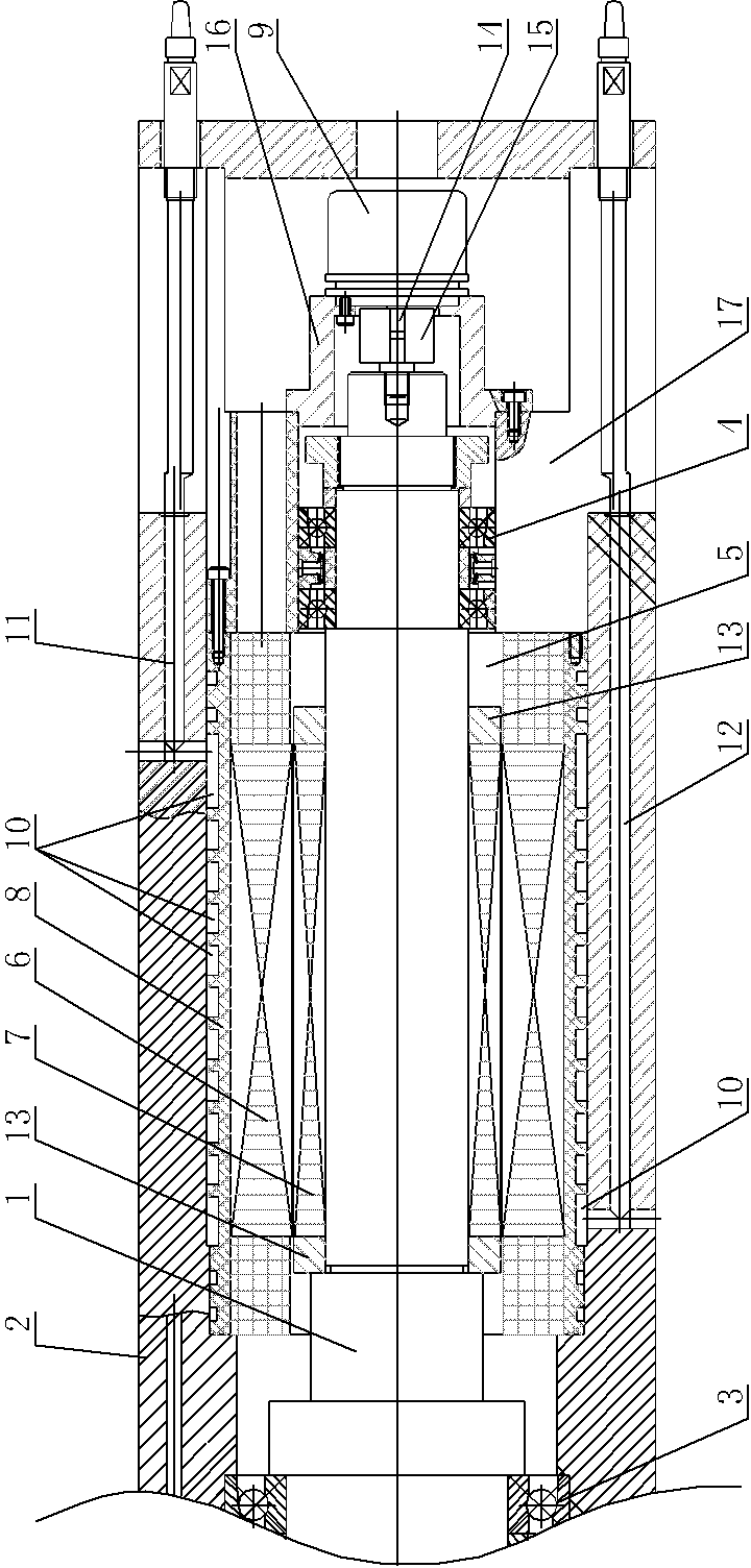
[0010] See figure 1 , which includes a main shaft 1, a sleeve 2, and a motor. The main shaft 1 is supported inside the sleeve 2 through the front bearing 3 and the rear bearing 4. The tail between the main shaft 1 and the sleeve 2 is provided with a motor installation cavity 5, and the motor is located in the motor installation The cavity 5 is characterized in that: the motor is a synchronous permanent magnet motor, which specifically includes a stator 6 and a rotor 7, the rotor 7 is set on the main shaft 1, the outer ring surface of the rotor 7 is wrapped with the stator 6, and the outer shell of the stator 6 8 is embedded in the outer end ring surface of the motor installation cavity 5, the tail of the main shaft 1 is provided with an encoder 9, and the outer shell 8 of the stator 6 is provided with an annular heat dissipation ring 10, and the adjacent heat dissipation rings 10 are connected to each other, and the sleeve The interior of 2 is respectively provided with water ...


PUM


Abstract

The invention provides a motor installing structure of a motorized spindle for grinding a railway bearing. According to the motor installing structure of the motorized spindle for grinding the railway bearing, an installing gap between the spindle and a sleeve is made to be small, the calorific value of a motor which is used is small, power conversion rate of the motor is high, and energy is saved. The motor installing structure of the motorized spindle for grinding the railway bearing comprises the spindle, the sleeve and the motor. The spindle is supported inside the sleeve through a front bearing pedestal and a rear bearing pedestal, a motor installation cavity is formed in the tail portion between the spindle and the sleeve, and the motor is arranged in the motor installation cavity. The motor installing structure of the motorized spindle for grinding the railway bearing is characterized in that the motor is a permanent magnet synchronous motor, the permanent magnet synchronous motor specifically comprises stators and rotors, the rotors are sleeved on the spindle, the outer annular surfaces of the rotors are covered by the stators, the outer shell bodies of the stators are embedded into the outer end annular face of the motor installation cavity, the tail portion of the spindle is provided with an encoder, and annular heat dissipation rings are arranged on the outer shell bodies of the stators.

Description

technical field [0001] The invention relates to the technical field of an electric spindle structure, in particular to a motor installation structure of an electric spindle used for grinding railway bearings. Background technique [0002] The existing electric spindle motors used for grinding railway bearings are all driven by ordinary asynchronous motors, which are large in size and require a large installation gap between the spindle and the sleeve, so that more materials are required to manufacture the sleeve, and the material cost is high , and its heat generation is large, resulting in a low power conversion rate and a waste of energy. Contents of the invention [0003] In view of the above problems, the present invention provides a motor installation structure for the electric spindle for grinding railway bearings, which makes the installation gap between the spindle and the sleeve small; and the used motor has a small calorific value and a high power conversion ...

Claims


Application Information

Patent Timeline
Patent Type & Authority Applications(China)
IPC IPC(8): B24B41/04H02K11/00H02K9/19H02K11/20
Inventor 朱凯旋缪云江
Owner WUXI MACHINETOOL
Why Eureka
Try Eureka