Coupling mechanism of shafts

A technology of coupling mechanism and driven shaft, which is applied to rigid shaft couplings, couplings, mechanical equipment, etc., can solve the problems of difficulty in meeting precision requirements, affecting service life, and difficulty in keyway processing, so as to reduce operation difficulty, The effect of shortening the working time and prolonging the service life

Inactive Publication Date: 2013-10-09
KUNSHAN KINGLAI HYGIENIC MATERIALS
View PDF7 Cites 2 Cited by
  • Summary
  • Abstract
  • Description
  • Claims
  • Application Information

AI Technical Summary

Problems solved by technology

[0002] In mechanical transmission, power transmission between shafts is often required. For example, power transmission is required between the main shaft of a centrifugal pump or self-priming pump and the main shaft of the motor. To achieve the above power transmission, it is first necessary to connect the main shaft of the motor to the pump. The main shaft is connected so that the two shafts rotate together to transmit motion or torque. The existing two-axis online mechanism is usually composed of a driving shaft, a driven shaft and a coupling element, specifically as figure 1 As shown, the end of the driving shaft 3 extends into the driven shaft 2, the driving shaft 3 and the driven shaft 2 are provided with key grooves respectively, and the coupling key 1 is arranged in the key grooves, and the sides are locked and fixed by headless hexagon socket screws 4 , although this kind of connection between the driving shaft and the driven shaft can realize the simultaneous rotation of the two shafts, it is difficult to process the key groove, and the accuracy is difficult to meet the requirements, especially the key groove in the driven shaft 2 is relatively deep, and the processing accuracy is higher. It is difficult to meet the requirements, so that the installation, maintenance and disassembly process of the coupling mechanism is relatively difficult, and it will also lead to unstable operation and seriously affect the service life

Method used


Image

  • Coupling mechanism of shafts
  • Coupling mechanism of shafts
  • Coupling mechanism of shafts

Examples


Embodiment Construction

[0015] The present invention will be described in further detail below in conjunction with accompanying drawing and specific embodiment

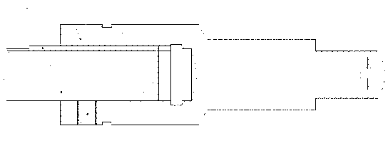
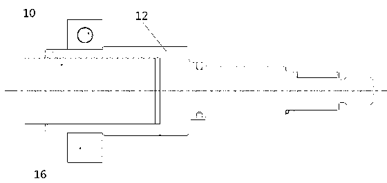
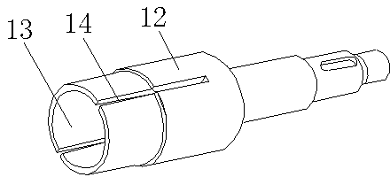
[0016] see Figure 2 to Figure 5 As shown, a shaft-to-shaft coupling mechanism of the present invention includes a driving shaft 10, a driven shaft 12 and a locking sleeve 16, wherein the end of the driven shaft 12 has a cavity 13 for accommodating the end of the driving shaft 10 (see image 3 ), the container 13 fits in shape with the end of the driving shaft 10. The special feature of the present invention is that two opening grooves 14 are provided on the side wall of the container 13 at intervals along its length (see image 3 ), the two open slots 14 are oppositely arranged, and the side wall of the container is divided into two parts arranged at intervals, and a locking sleeve 16 is set on the wall of the container. When in use, firstly, the end of the drive shaft 10 Extend into the slot 13 of the driven shaft 12, and then tighten th...


PUM


Abstract

The invention discloses a coupling mechanism of shafts. The coupling mechanism comprises the driving shaft (10) and the driven shaft (12), wherein the end portion of the driven shaft (12) is provided with a containing groove (13) for containing the end portion of the driving shaft (10). The coupling mechanism is characterized in that the side wall of the containing groove (13) is provided with at least two open grooves (14) at intervals in the length direction of the containing groove (13), and a locking sleeve (16) is sleeved at one end, provided with the containing groove (13), of the driven shaft (12). The coupling mechanism has the advantages of being safe, reliable, long in service life, and convenient to install, maintain and dismount.

Description

technical field [0001] The invention relates to a coupling mechanism, in particular to a shaft-to-shaft coupling structure. Background technique [0002] In mechanical transmission, power transmission between shafts is often required. For example, power transmission is required between the main shaft of a centrifugal pump or self-priming pump and the main shaft of the motor. To achieve the above power transmission, it is first necessary to connect the main shaft of the motor to the pump. The main shaft is connected so that the two shafts rotate together to transmit motion or torque. The existing two-axis online mechanism is usually composed of a driving shaft, a driven shaft and a coupling element, specifically as figure 1 As shown, the end of the driving shaft 3 extends into the driven shaft 2, the driving shaft 3 and the driven shaft 2 are provided with key grooves respectively, and the coupling key 1 is arranged in the key grooves, and the sides are locked and fixed by he...

Claims


Application Information

Patent Timeline
Patent Type & Authority Applications(China)
IPC IPC(8): F16D1/04
Inventor 李水波姚兴珍
Owner KUNSHAN KINGLAI HYGIENIC MATERIALS
Why Eureka
Try Eureka