
In-vehicle air monitoring and purification device and control method thereof

A technology for purifying devices and air in cars, applied in measuring devices, heating and ventilation control systems, heating methods, etc., can solve problems such as single function, inability to monitor harmful gases in real time, and large volume

Inactive Publication Date: 2015-12-23
WUHAN UNIV OF TECH
View PDF8 Cites 0 Cited by
  • Summary
  • Abstract
  • Description
  • Claims
  • Application Information

AI Technical Summary

Problems solved by technology

Most of the car air purifiers on the market use filter mesh, physical adsorption, and negative ion discharge to purify the air in the car. They only have the purification function, and cannot monitor various harmful gases in the car in real time and automatically turn on or off the purification according to the monitoring results. function; and the purifiers with better purification effect are mostly cuboid in shape, larger in volume, and there is a problem of limited location in the car, while the smaller in-car air purifier has single function, unsatisfactory purification effect and cannot be real-time Measure, the car can not continue to work after the engine is turned off

Method used


Image

  • In-vehicle air monitoring and purification device and control method thereof
  • In-vehicle air monitoring and purification device and control method thereof
  • In-vehicle air monitoring and purification device and control method thereof

Examples


Embodiment Construction

[0050] The present invention will be further described below in conjunction with specific examples and accompanying drawings.

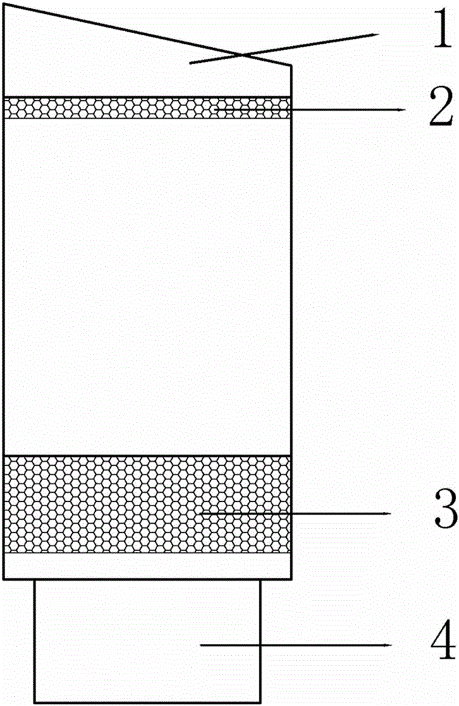
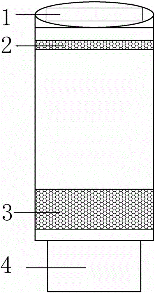
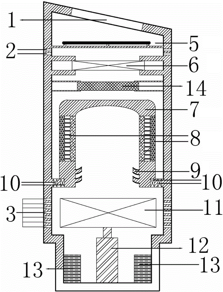
[0051] figure 1 It is a structural schematic diagram of an embodiment of the present invention, figure 2 for figure 1 right view of the image 3 for figure 1The sectional view of it comprises a housing and a base 4, the top of the housing is provided with a display screen 1, and the bottom of the housing is connected to the base 4 (the base 4 is cylindrical in this embodiment, and the outer diameter is equal to the inner diameter of the vehicle-mounted water cup groove, and can be used during use. directly into the water cup tank of the vehicle), the upper part of the housing is provided with an air outlet grid 2, and the lower part of the housing is provided with an air intake grid 3. Optionally, a filter is provided in the air intake grid to filter large particles of dust The inside of the housing is divided into upper and lower cavities by the...


PUM


Abstract

The invention provides an in-vehicle air monitoring and purification device and a control method of the in-vehicle air monitoring and purification device. The in-vehicle air monitoring and purification device comprises a shell and a base, wherein a display screen is arranged at the top end of the shell, the bottom of the shell is connected with the base, an air outlet grid is arranged on the upper portion of the shell, and an air inlet grid is arranged on the lower portion of the shell. The interior of the shell is divided by an air purification assembly into an upper cavity and a lower cavity, a sensor set for detecting harmful gas in air, a turbine and a turbine motor are arranged in the lower cavity, and a negative-ion generator and an air blower are sequentially arranged in the upper cavity in the air delivery direction. A power source is fixed in the base. The in-vehicle air monitoring and purification device further comprises a control circuit, and the control circuit comprises an analog-digital conversion circuit, a single-chip microcomputer, a charging circuit and an executing mechanism. By means of the in-vehicle air monitoring and purification device and the control method of the in-vehicle air monitoring and purification device, the in-vehicle air quality can be monitored in real time, the purification function can be automatically started when the in-vehicle air quality exceeds the safety index value, and the purification function can be automatically stopped after the in-vehicle air quality reaches the standard.

Description

technical field [0001] The invention belongs to a car interior air purifier, in particular to a car interior air monitoring and purification device and a control method thereof. Background technique [0002] For the environmental pollution in the car, the World Health Organization has clearly listed it as one of the top ten threats to human health together with high blood pressure and AIDS. On October 27, 2011, the Ministry of Environmental Protection and the General Administration of Quality Supervision, Inspection and Quarantine jointly issued the "Guidelines for the Evaluation of Air Quality in Passenger Cars" (GB / T27630-2011), which stipulated the concentration of 8 common volatile organic compounds in the air in the car. Set the limit value and officially implement it from March 1, 2012. Most of the car air purifiers on the market use filter mesh, physical adsorption, and negative ion discharge to purify the air in the car. They only have the purification function, and...

Claims


Application Information

Patent Timeline
Patent Type & Authority Patents(China)
IPC IPC(8): F24F1/02F24F13/28F24F11/02G01N33/00
CPCY02B30/70
Inventor 王宇宁蔡永华李能武袁昊胡斌祥张智
Owner WUHAN UNIV OF TECH
Learn More