System and method for measuring bridge deflection based on close-range photographic measurement

A technology of bridge deflection and close-range photography, which is applied in the direction of measuring devices, elastic testing, and machine/structural component testing, etc. It can solve problems such as the inability to install contact displacement measuring instruments, achieve comprehensive and objective image display information, and save labor costs. , Reduce the effect of field work

Inactive Publication Date: 2013-10-09
JILIN UNIV
View PDF6 Cites 36 Cited by
  • Summary
  • Abstract
  • Description
  • Claims
  • Application Information

AI Technical Summary

Problems solved by technology

[0003] The technical problem to be solved by the present invention is to overcome the problem that the contact displacement measuring instrument in the prior art cannot be installed in a special environment, to provide a bridge deflection measurement system based on close-range photogrammetry technology, and to provide a bridge deflection measurement system based on Measuring method of bridge deflection measuring system based on close-range photogrammetry

Method used


Image

  • System and method for measuring bridge deflection based on close-range photographic measurement
  • System and method for measuring bridge deflection based on close-range photographic measurement
  • System and method for measuring bridge deflection based on close-range photographic measurement

Examples


Embodiment

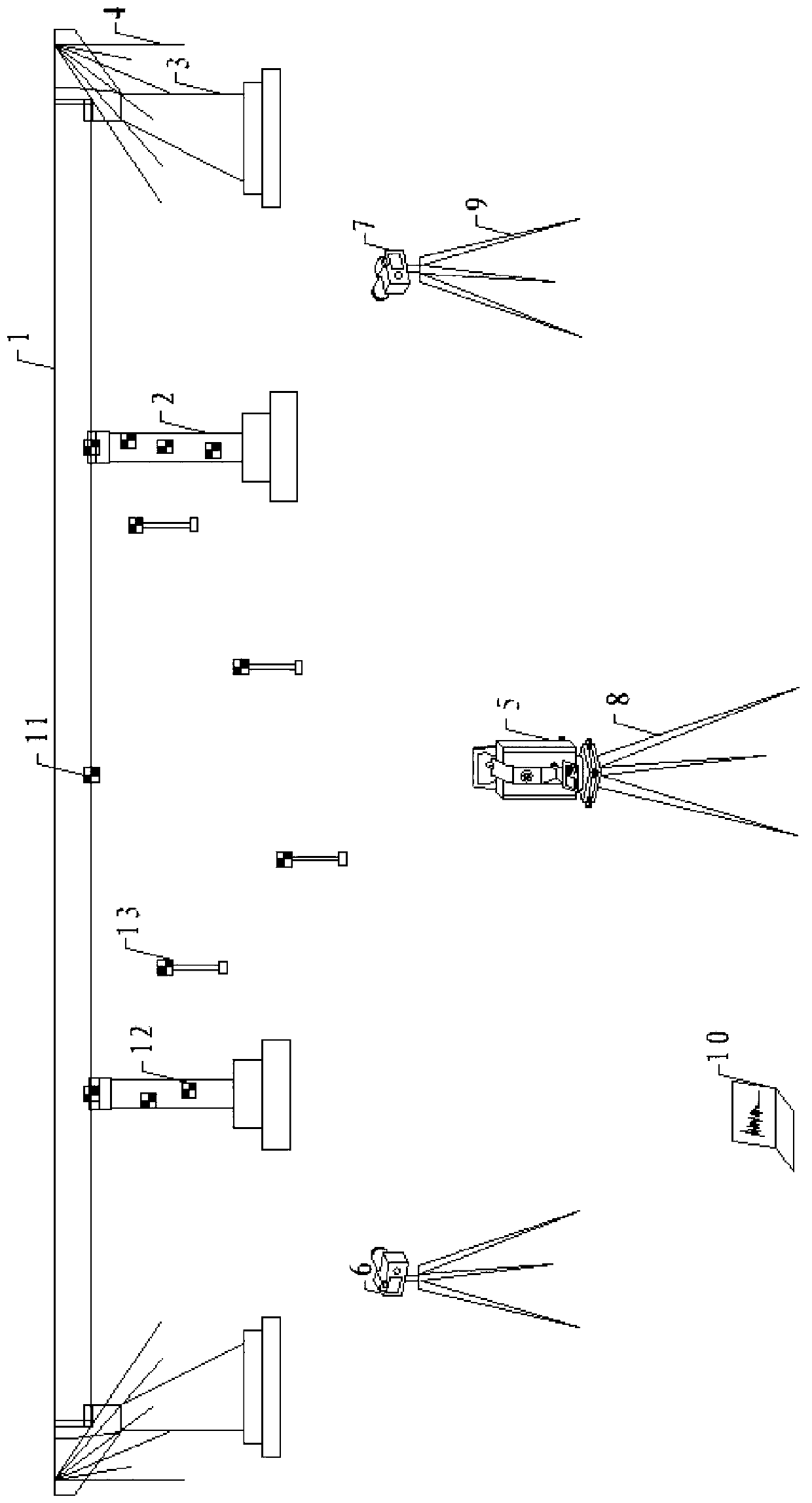
[0119] The bridge deflection measurement system based on close-range photogrammetry described above in the present invention is used for measurement. The object of this measurement is a wooden material with low rigidity and easy to bend and deform to simulate a concrete beam, and a cylindrical steel cylinder is used to simulate a bridge pier. During the measurement process, a load is applied to the wooden board to make it reach a certain deformation, so that the overall deflection curve is similar to that of conventional concrete. The deflection curves of the beams after deformation are almost the same; the target point 11, the control point 12 placed on the pier, and the control point 13 placed on the pole are installed at a higher position in combination with the camera position, so that the No. 1 single-lens reflex camera 6 and No. 2 No. single-lens reflex camera 7 is used to perform overhead imaging, which is similar to the actual bridge position; simulate the actual situat...


PUM


Abstract

The invention discloses a system and method for measuring bridge deflection based on close-range photographic measurement. According to the system and method for measuring the bridge deflection based on the close-range photographic measurement, the problem that in a special environment, a contact type displacement measuring instrument can not be installed is solved. The system for measuring the bridge deflection based on the close-range photographic measurement comprises a total station, two single-lens light reflection cameras, an industrial control computer, 4-5 control points arranged on piers, 6-8 control points arranged on uprights and three target points. The measuring distance of the total station is 5m-50m and the shooting distance of the two single-lens light reflection cameras is 3m-15m; the three target points are located on supporting point portions and in the middle of each stride of the bridge, the control points arranged on the piers are arranged on two piers, and the control points arranged on the uprights are arranged below and in front of the three target points. The distance between the abscissa and the ordinate of every two adjacent control points of the control points arranged on the piers and the control points arranged on the uprights is 3m-10m. The industrial control computer and the two single-lens light reflection cameras are connected through signal lines. The invention further provides the measuring method.

Description

technical field [0001] The invention relates to a measurement system and a measurement method, more precisely, the invention relates to a bridge deflection measurement system and method based on close-range photogrammetry. Background technique [0002] Bridge deflection detection is an important task to evaluate the operation status of the bridge according to its structural characteristics and bearing capacity in the static load test. The highway management and maintenance department can effectively prevent the instantaneous partial damage of the bridge by grasping the health status of the existing bridge in real time , collapse and other major accidents. The traditional detection methods of bridge detection in our country usually need to use instruments such as dial gauges and displacement meters for contact measurement work, which has the advantages of simplicity and low cost; When the bridge crosses obstacles such as rivers, rivers, mountain streams, and railways, it is ...

Claims


Application Information

Patent Timeline
Patent Type & Authority Applications(China)
IPC IPC(8): G01M5/00G01B11/16
Inventor 刘寒冰王琬婷程永春魏海斌焦峪波王龙林李理罗国宝张仰鹏王叶丹
Owner JILIN UNIV
Why Eureka
Try Eureka