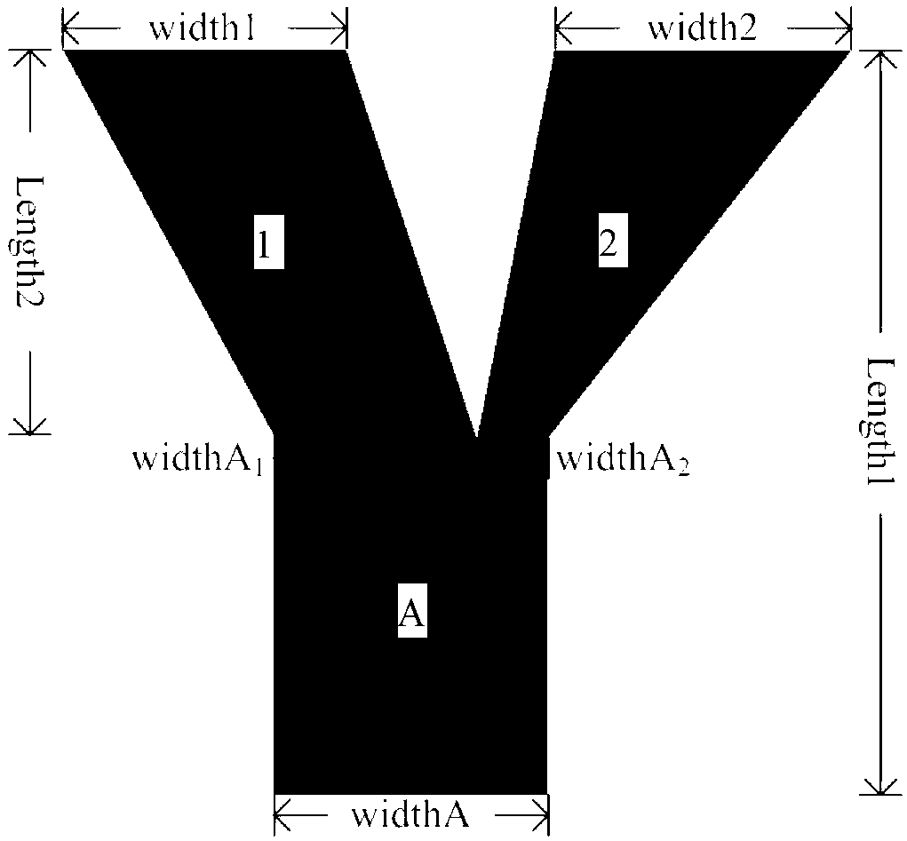
Asymmetric planar optical waveguide mode multiplexing/demultiplexing device based on few-mode fibers
A planar optical waveguide and few-mode optical fiber technology, applied in the field of communication, can solve problems such as difficult productization, large insertion loss, and difficult interconnection
- Summary
- Abstract
- Description
- Claims
- Application Information
AI Technical Summary
Problems solved by technology
Method used
Image
Examples
Embodiment 1
[0053] Embodiment 1: When a single mode is input to the fundamental mode, the fundamental mode is transmitted in the waveguide.
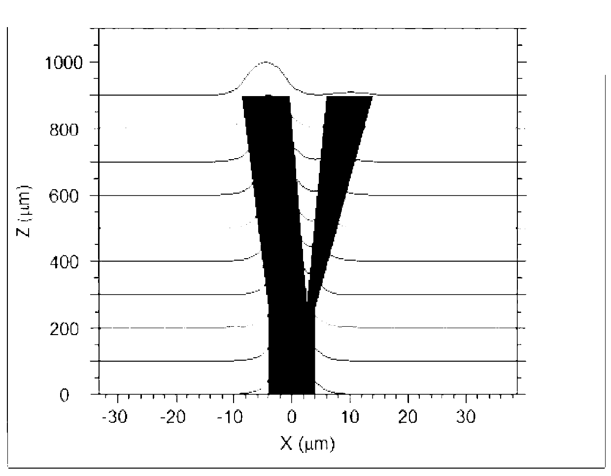
[0054] In this embodiment, the light input into the waveguide is controlled at the input end of the waveguide, and only the fundamental mode is selected in the incident light. Schematic diagram of the flow process of field energy in the waveguide when the fundamental mode is injected into the main arm A of the waveguide, as shown in image 3 shown. It can be clearly seen from the figure that after the fundamental mode enters the main arm, it is transmitted forward. When it is transmitted to the bifurcation, the power of the fundamental mode in the branch arm 1 remains basically unchanged, and most of the energy in the light wave travels along the branch arm. 1 spread. The power of the fundamental mode in branch arm 2 drops rapidly from the bifurcation, reaches the lowest value when it reaches about 600 μm, and remains stable until the end. The ou...
Embodiment 2
[0057] Embodiment 2: When a single mode is input to a first-order mode, the first-order mode is transmitted in the waveguide.
[0058] The light input into the waveguide is controlled at the input end of the waveguide, and the fundamental mode is converted into a first-order mode through mode conversion, and then it is incident into the main arm A of the waveguide. Schematic diagram of the flow process of field energy in the waveguide when the first-order mode is injected into the main arm A of the waveguide, as shown in Figure 6 shown. It can be seen from the figure that after the first-order mode enters the waveguide, it is normally transmitted within the range of the main arm, but after passing through the branch point, the energy of the first-order mode flows to the branch arm 2, and is converted into the fundamental wave during the transmission process of the branch arm 2. mode, the power of the fundamental mode in branch arm 2 increases gradually, and basically reaches...
Embodiment 3
[0062] Embodiment 3: When the fundamental mode and the first-order mode are input at the same time, the fundamental mode and the first-order mode are transmitted in the waveguide.
[0063] When the fundamental mode and the first-order mode are simultaneously injected into the main arm A of the waveguide, the propagation of the optical mode in the waveguide at this time is observed. Since the effective refractive index of the fundamental mode in waveguide A is similar to the effective refractive index of the fundamental mode in branch arm 1, the fundamental mode is output along branch arm 1 after matching; the effective refractive index of the first-order mode in waveguide A is the same as that of the fundamental mode in branch arm 2 Approximate, so after matching, the first-order mode is converted to the fundamental form and output along branch arm 2.
[0064] When the fundamental mode and the first-order mode are injected into the main arm A of the waveguide at the same time,...
PUM
 Abstract
Description
Claims
Application Information
 - R&D
- Intellectual Property
- Life Sciences
- Materials
- Tech Scout
- Unparalleled Data Quality
- Higher Quality Content
- 60% Fewer Hallucinations
Browse by: Latest US Patents, China's latest patents, Technical Efficacy Thesaurus, Application Domain, Technology Topic, Popular Technical Reports.
© 2025 PatSnap. All rights reserved.Legal|Privacy policy|Modern Slavery Act Transparency Statement|Sitemap|About US| Contact US: help@patsnap.com


