
Pixel drive circuit

A technology of pixel driving circuit and pixel electrode, which is applied in the direction of instruments, static indicators, etc., can solve the problems of poor transmittance, achieve better transmittance performance, improve the effect of side view color shift, and large tilting angle

Active Publication Date: 2016-01-20
AU OPTRONICS CORP
View PDF7 Cites 0 Cited by
  • Summary
  • Abstract
  • Description
  • Claims
  • Application Information

AI Technical Summary

Problems solved by technology

However, the output voltage of the current general-purpose integrated circuit is only up to 16V, and the voltage gap felt by the liquid crystal is not enough to drive the electrode spacing larger than 16um, so that the penetration rate of the wider electrode spacing is not good, and wider electrodes cannot be used. Spacing to further improve side view color cast

Method used


Image

  • Pixel drive circuit
  • Pixel drive circuit
  • Pixel drive circuit

Examples


Embodiment Construction

[0064] The detailed features and advantages of the present invention are described in detail below in the embodiments, the content of which is sufficient for any skilled person familiar with the relevant knowledge to understand the technical content of the present invention and implement it accordingly, and according to the content disclosed in this specification, the claims and the appended Any skilled person who is familiar with relevant knowledge can easily understand the related objects and advantages of the present invention. The following examples further illustrate the viewpoints of the present invention in detail, but limit the scope of the present invention in any way.

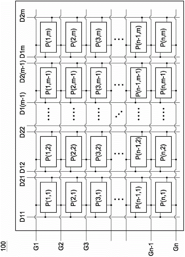
[0065] Please refer to figure 1 , is a schematic diagram of a circuit structure of a pixel matrix 100 . The pixel matrix 100 includes a plurality of scanning lines G1, G2...Gn-1, Gn, a plurality of first data lines D11, D12...D1(m-1), D1m, a plurality of second data lines D21, D22... D2(m-1), D2m an...


PUM


Abstract

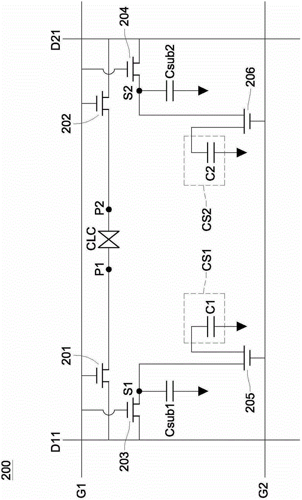
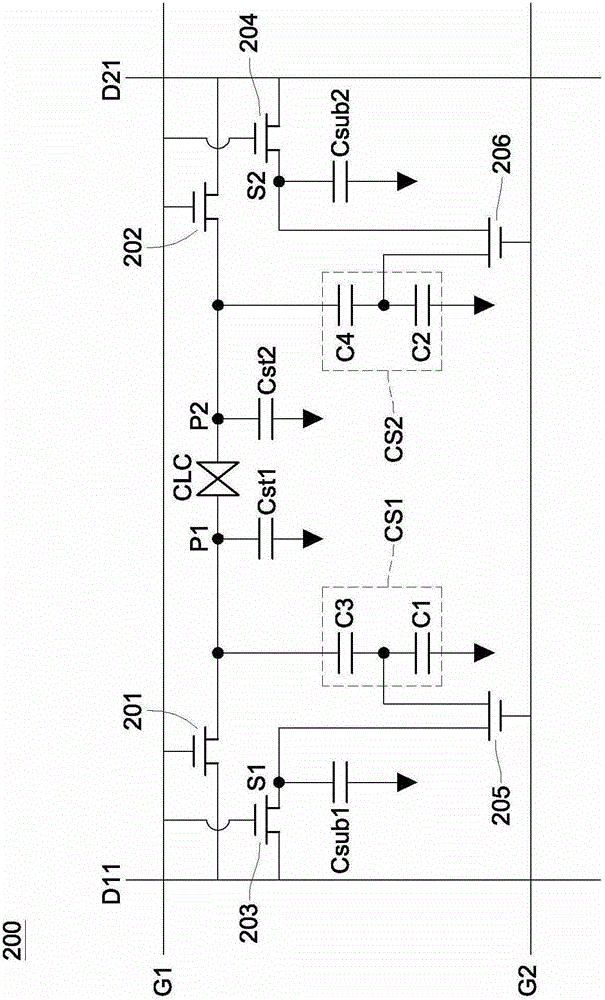
A driving circuit electrically coupled between a first data line and a second data line and between a first scan line and a second scan line. The driving circuit includes a first switch, a second switch, a third switch, a fourth switch, a first sub-capacitor, a second sub-capacitor, a fifth switch, a sixth switch, a first voltage dividing unit and a second voltage dividing unit. The first voltage dividing unit is coupled between a second end of the fifth switch and a reference voltage end. The second voltage dividing unit is coupled between a second end of the sixth switch and the reference voltage end, for redistributing stored electric charges.

Description

technical field [0001] The present invention relates to a pixel driving circuit, in particular to a pixel driving circuit for improving pixel transmittance. Background technique [0002] As liquid crystal display devices continue to develop towards large-size display specifications, in order to overcome the viewing angle problem under large-size displays, the wide viewing angle technology of liquid crystal display panels must also continue to improve and break through. Technologies that can meet the requirements of wide viewing angle include, for example, multi-domain vertical alignment (MVA), multi-domain horizontal alignment (MHA), twisted nematic plus viewing angle expansion film (TN+film) and transverse electric field (InPlane Switching, IPS). [0003] The liquid crystal display using the technologies listed above can achieve the purpose of wide viewing angle, but there will be a problem of color washout. Generally speaking, the so-called color shift means that when the...

Claims


Application Information

Patent Timeline
Patent Type & Authority Patents(China)
IPC IPC(8): G09G3/36
CPCG09G3/3648G09G3/3659G09G2300/0447G09G2300/0852G09G2320/028
Inventor 曹韶文龚晏莹陈卓彦吕美如丁天伦
Owner AU OPTRONICS CORP
Learn More