Dehumidification device and dehumidification method

A sensor and heat dissipation chamber technology, applied in the field of refrigeration equipment, can solve the problems of insufficient dehumidification and heat dissipation, large volume, and water molecules discharged out of the box, so as to improve the heat dissipation effect, strengthen the heat dissipation effect, and ensure the effect of normal work.

Active Publication Date: 2013-10-09
苏州市远帆电器有限公司
View PDF5 Cites 25 Cited by
  • Summary
  • Abstract
  • Description
  • Claims
  • Application Information

AI Technical Summary

Problems solved by technology

[0003] Existing industrial dehumidifiers mostly adopt the principle of fluorine refrigeration, which is bulky and inconvenient to install in distribution cabinets; therefore, most of the existing dehumidification in distribution cabinets adopts the method of humidity controller + heater. Molecules are discharged out of the box, only to increase the temperature inside the box, so that the water vapor does not condense into dewdrops; because the air moisture in the box is in an unsaturated state, when the box is not well sealed, the water vapor outside the box w

Method used


Image

  • Dehumidification device and dehumidification method
  • Dehumidification device and dehumidification method
  • Dehumidification device and dehumidification method

Examples


Embodiment 1

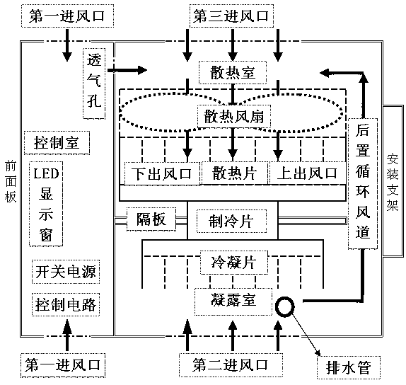
[0036] Such as Figure 1-2 As shown, a dehumidification device is fixedly installed in the cabinet of the electrical distribution box using C45 rails, including a housing, a dehumidification and heat dissipation device, a control device and a threshold value correction device.

[0037] The housing includes a heat dissipation chamber, a condensation chamber and a control chamber. The control chamber is arranged in the front cavity of the casing, and the heat dissipation chamber and the condensation chamber are arranged side by side in the rear chamber of the casing; There is a baffle; there is also a partition between the condensation room and the control room to prevent temperature conduction.

[0038] Dehumidification and heat dissipation device, including semiconductor cooling fins, condensation fins, fans, cooling fins and circulating air ducts, the condensation fins are installed in the condensation chamber, the fan and cooling fins are installed in the cooling chamber, an...

Embodiment 2

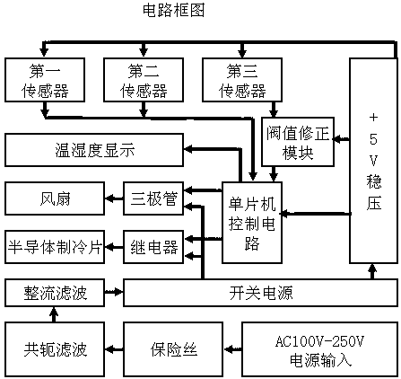
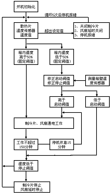
[0055] The rest are the same as in Embodiment 1, the difference is that due to the limitation of installation conditions, the third sensor in the detection device is not installed, but the temperature adjustment difference program is preset in the threshold value correction module, when the temperature in the box reaches a certain temperature When the value is set, the system performs the set temperature compensation according to the current temperature value, and adjusts the relevant threshold value according to the compensation value.

Embodiment 3

[0057] The rest is the same as in Example 1, except that the dehumidification device is installed in the knife mechanism box by strong magnetic adsorption; there is also a movable baffle for adjusting the air flow in the rear circulating air duct, which is used to adapt to the south or north. different climatic conditions.


PUM


Abstract

A dehumidification device comprises a shell body, a dehumidification radiator, a control device and a threshold value correcting device, wherein the radiator comprises cooling fins used for dissipating heat and condensing fins used for dehumidification and is used for refrigeration of the condensation fins and transmitting heat of the condensation fins to the cooling fins; the control device is used for detecting temperatures and humidity inside and outside of a box and the temperature of the cooling fins and is used for receiving detection signals of a detection device and carrying out corresponding data processing and control output; the threshold value correcting device is used for correcting a starting or stopping threshold value according to an inside and outside environment difference value. The dehumidification device is used for dehumidification operation inside a box body of an electric distribution box, semiconductor refrigeration dehumidification and full-electronic control are adopted, the starting threshold value can be automatically corrected according to the real working environment, dehumidification and heat dissipation effects can be reliable, and pollution does not exist. The invention further discloses a dehumidification method.

Description

technical field [0001] The invention relates to a refrigeration device, in particular to a dehumidification device used for dehumidification and drying inside an electric distribution box cabinet. Background technique [0002] The humidity in the air is as ubiquitous as the temperature. If the humidity in the room is too high, people will feel hot and uncomfortable. At the same time, when the relative humidity of the environment is greater than 60%, mold can grow. At the same time, equipment damage caused by moisture and mold to metal oxidation can occur unconsciously at any time. With the advancement of science and technology and the continuous improvement of product technology, its new production process and high requirements for environmental temperature, humidity and cleanliness in the production process, industrial dehumidifiers have begun to be widely used in large computer rooms, industrial workshop warehouses, file management , underground engineering and other impo...

Claims


Application Information

Patent Timeline
IPC IPC(8): H02B1/56G05D27/02
Inventor 方海钰张长知李凯
Owner 苏州市远帆电器有限公司
Why Eureka
Try Eureka