Method for realizing digital angle converter and digital angle switching circuit of digital angle converter

A technology of angle conversion and implementation method, applied in the direction of digital-to-analog converters, etc., can solve problems such as high cost, difficult to purchase, and affect design, and achieve the effect of convenient conversion of digital angle values, easy procurement and implementation, and guaranteed reliability

Inactive Publication Date: 2013-10-09
NO 771 INST OF NO 9 RES INST CHINA AEROSPACE SCI & TECH
View PDF3 Cites 1 Cited by
  • Summary
  • Abstract
  • Description
  • Claims
  • Application Information

AI Technical Summary

Problems solved by technology

[0002] Traditional angle conversion circuits are realized by professional DRC chips, and these professional chips are expensive and basically imported from abroad, such as AD2S65 / 66, DRC1745 / 1746, etc.
These chips are mixed packaging circuits, which are expensive and subject to foreign factors, such as production suspension and embargo, which will affect the original design and even require a new DRC design method to achieve
Existing digital angle conversion circuits are usually realized by a core digital angle chip, which is expensive and difficult to purchase; and there are currently some angle conversion circuit technologies built with high-precision DA, which are relatively expensive to implement , not easy to implement

Method used


Image

  • Method for realizing digital angle converter and digital angle switching circuit of digital angle converter
  • Method for realizing digital angle converter and digital angle switching circuit of digital angle converter
  • Method for realizing digital angle converter and digital angle switching circuit of digital angle converter

Examples


Embodiment Construction

[0026] The present invention will be further described in detail below in conjunction with specific embodiments, which are explanations of the present invention rather than limitations.

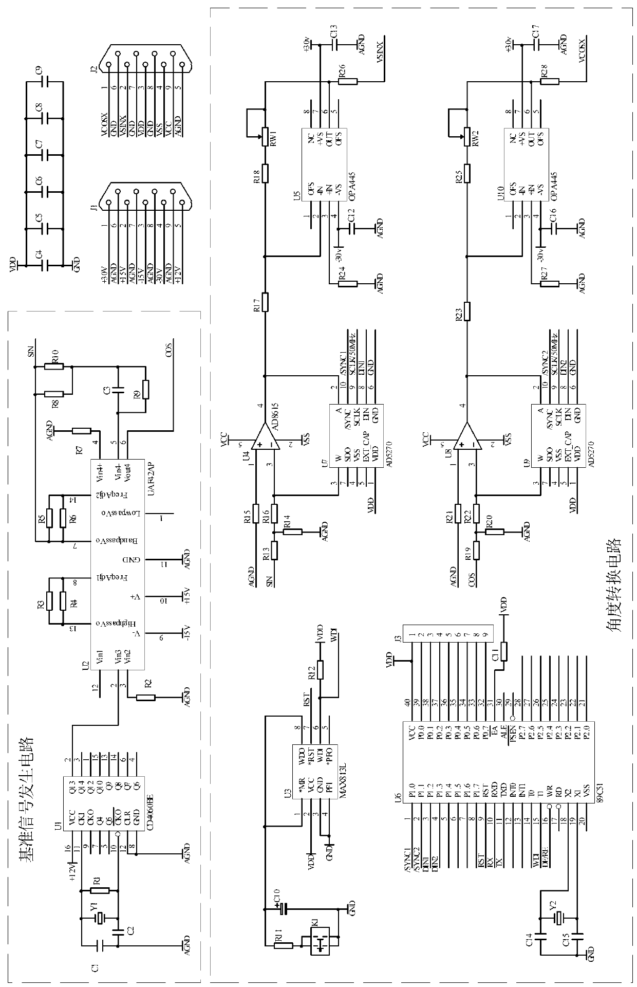
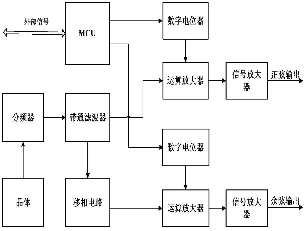
[0027] Such as figure 1 Therefore, a digital angle conversion circuit of the present invention includes a sine-cosine reference generation circuit, an angle analysis and conversion circuit and a signal amplification circuit, the signal amplification circuit includes a signal amplifier; the angle analysis and conversion circuit includes an MCU, two digital potentials and two operational amplifiers; the MCU is used to receive and analyze external command signals, and realize the sinusoidal signal output through a digital potentiometer and an operational amplifier connected in sequence, and realize the output through another digital potentiometer and another operational amplifier connected in sequence The output of the cosine signal; the sine and cosine reference generating circuit respectively ...


PUM


Abstract

The invention relates to a method for achieving a digital angle converter and a digital angle switching circuit of the digital angle converter. The switching circuit is simple in structure and high in reliability. The switching circuit comprises a sine-and-cosine standard generating circuit, an angle analyzing and converting circuit and a signal amplifying circuit. The signal amplifying circuit comprises a signal amplifier. The angle analyzing and converting circuit comprises an MCU, two digital potentiometers and two operational amplifiers. The achieving method is simple in operation and high in precision. The method includes the following steps that when an external command signal is written into a temporary storage of the MCU, the MCU analyzes an angle value theta in the command signal, the angle value theta is converted into an operational amplifier gain number value which corresponds to a sine and a cosine, the analyzed angle data are transmitted to the two digital potentiometers respectively, conversion of the angle value theta, a corresponding sine analog value and a corresponding cosine analog value is achieved through change of gain of the operational amplifier, and a converted sine signal and a converted cosine signal, after respectively amplified through the corresponding signal amplifier in the signal amplifying circuit, are output.

Description

technical field [0001] The invention belongs to the technical field of computer applications, and in particular relates to a method for realizing a digital angle converter and a digital angle conversion circuit thereof. Background technique [0002] Traditional angle conversion circuits are realized by professional DRC chips, and these professional chips are expensive and basically imported from abroad, such as AD2S65 / 66, DRC1745 / 1746 of AD, etc. These chips are all mixed packaging circuits, which are expensive and subject to foreign restrictions. Unfavorable factors such as production stoppages and embargoes will affect the original design, and even require a new DRC design method to achieve. Existing digital angle conversion circuits are usually realized by a core digital angle chip, which is expensive and difficult to purchase; and there are currently some angle conversion circuit technologies built with high-precision DA, which are relatively expensive to implement , is...

Claims


Application Information

Patent Timeline
Patent Type & Authority Applications(China)
IPC IPC(8): H03M1/66
Inventor 王琛苏理段晓飞
Owner NO 771 INST OF NO 9 RES INST CHINA AEROSPACE SCI & TECH
Why Eureka
Try Eureka