
Smart Antenna Selection Method and Access Point

A smart antenna and access point technology, applied in the field of communication, can solve the problems of decreased training accuracy, small user traffic demand, small traffic per unit time, etc., and achieve the effect of increased air interface utilization

Active Publication Date: 2016-06-29
RUIJIE NETWORKS CO LTD
View PDF9 Cites 0 Cited by
  • Summary
  • Abstract
  • Description
  • Claims
  • Application Information

AI Technical Summary

Problems solved by technology

However, the existing technology cannot distinguish whether the user's traffic is small because the user's own traffic demand is small, or the rate is low due to the harsh environment, which causes the traffic per unit time to be small.
For STAs with low rate due to the harsh environment and small traffic per unit time, it is impossible to select the optimal antenna array for a long time
At the same time, due to the shared nature of the wireless network, in the integrated network, if there are individual STAs with poor initial communication quality, it will inevitably affect the normal communication of other STAs. During the smart antenna training process, even if individual STAs with better communication quality The STA quickly selects the optimal antenna array. If some STAs are unable to select the optimal antenna array for a long time due to the poor communication environment of some STAs, the communication quality of the entire network will be severely affected in terms of air interface utilization. Large impact, and the training time is long, the accuracy of the training may also decrease due to factors such as changes in the STA position

Method used


Image

  • Smart Antenna Selection Method and Access Point
  • Smart Antenna Selection Method and Access Point
  • Smart Antenna Selection Method and Access Point

Examples


Embodiment Construction

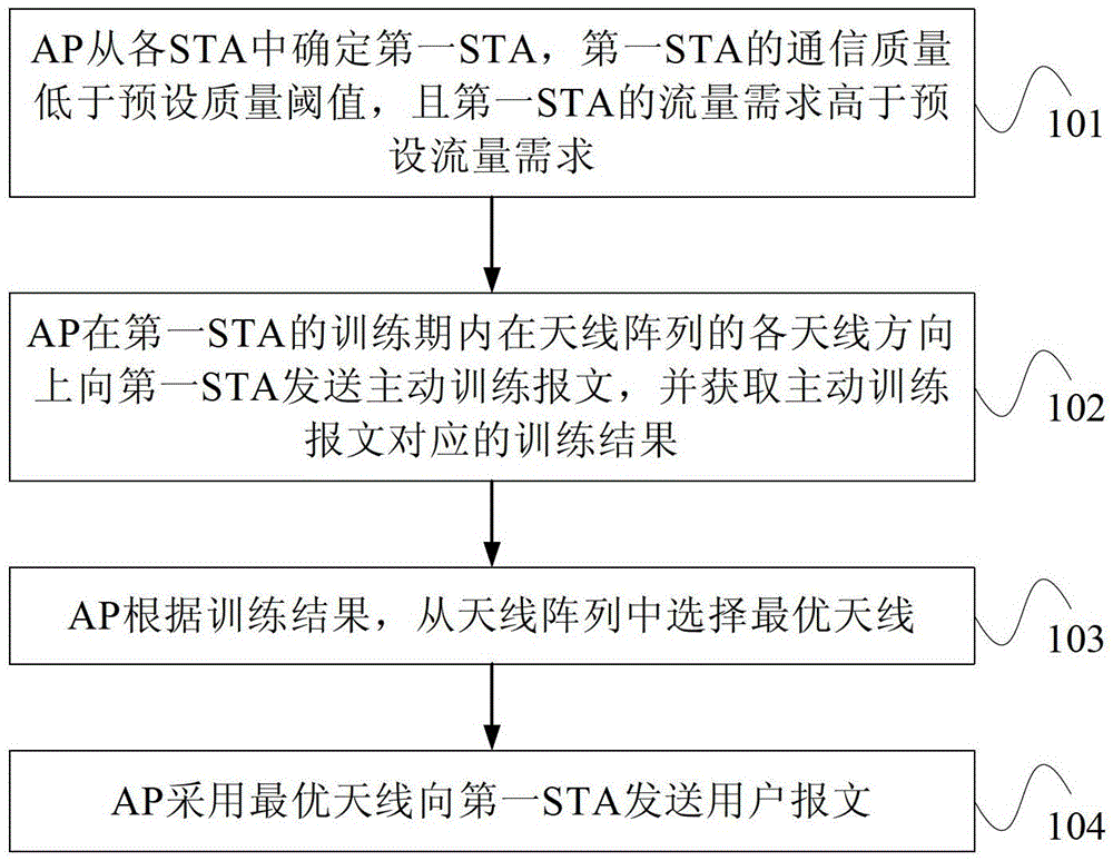
[0040] figure 1 It is a flow chart of Embodiment 1 of the smart antenna selection method of the present invention, as figure 1 As shown, the method for selecting a smart antenna provided in this embodiment specifically includes the following steps:

[0041] In step 101, the AP determines a first STA from the STAs, the communication quality of the first STA is lower than a preset quality threshold, and the traffic demand of the first STA is higher than the preset traffic demand.

[0042] When the AP has data to send to each STA, the communication quality and traffic demand of each STA are obtained, and the STA whose communication quality is lower than a preset quality threshold and whose traffic demand is higher than the preset traffic demand is determined as the first STA. Among them, each STA refers to all STAs connected to the AP. The communication quality can be determined according to the rate, packet loss rate, and signal strength indication of the STA. The traffic deman...


PUM


Abstract

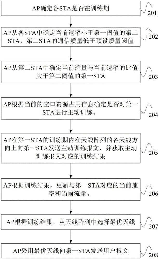
The invention provides a method for selecting an intelligent antenna and an access point. The method for selecting the intelligent antenna comprises the steps that (1) the AP determines a first station from stations, the value of the communication quality of the first STA is smaller than a preset quality threshold value, and the flow requirement of the first STA is higher than a preset flow requirement; (2) the AP sends an active training message to the first STA in the directions of antennas of an antenna array in a training period of the first STA, and obtains a training result which corresponds to the active training message; (3) the AP selects an optimal antenna from the antenna array according to the training result; (4) the AP uses the optimal antenna to send a user message to the first STA. According to the method for selecting the intelligent antenna, due to the facts that the AP sends the active training message to the first STA which is poor in communication quality but has a certain need for flow, and increases user flow by sending the active training message, the AP helps the first STA to select the optimal antenna as soon as possible.

Description

technical field [0001] The invention relates to communication technology, in particular to a method for selecting an intelligent antenna and an access point. Background technique [0002] Traditional antennas have the disadvantages of large coverage angles but small coverage areas. With the emergence of smart antennas, different antenna array combinations can be dynamically selected, which can not only achieve full coverage of all angles, but also obtain greater coverage at each angle. scope. When the access point (AccessPoint, referred to as AP) needs to select the most suitable antenna array for the station (STATION, referred to as STA), the AP can send messages to the antenna array in different directions, and then select the optimal antenna array through a series of judgment strategies. Antenna array to ensure the transmission quality as much as possible. [0003] In the prior art, the selection of the antenna array depends on the normal user traffic, and the training ...

Claims


Application Information

Patent Timeline
Patent Type & Authority Patents(China)
IPC IPC(8): H04B7/04H04W88/08H04L1/16
Inventor 黄增安
Owner RUIJIE NETWORKS CO LTD
Learn More