LED driving circuit

A technology of LED driving and driving control circuit, applied in the field of electronics, can solve the problems such as damage to the driving chip U1, poor safety, and increase of use cost, etc.

Inactive Publication Date: 2013-10-09
潍坊晶兰电源技术有限公司
View PDF9 Cites 5 Cited by
  • Summary
  • Abstract
  • Description
  • Claims
  • Application Information

AI Technical Summary

Problems solved by technology

[0003] In the process of realizing the present invention, the inventors have found that there are at least the following problems in the prior art: because the field effect transistor Q1 is a vulnerable part, it is prone to breakdown damage, and when the field effect transistor Q1 breaks down, the drain of the field effect transistor Q1 The high voltage is directly applied to the grid, and is added to the drive output terminal of the driver chip U1 through the resistor R13 and the diode D11, so that the driver chip U1 is damaged, the safety is poor, and the use cost is increased.

Method used


Image

  • LED driving circuit
  • LED driving circuit
  • LED driving circuit

Examples


Embodiment Construction

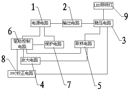
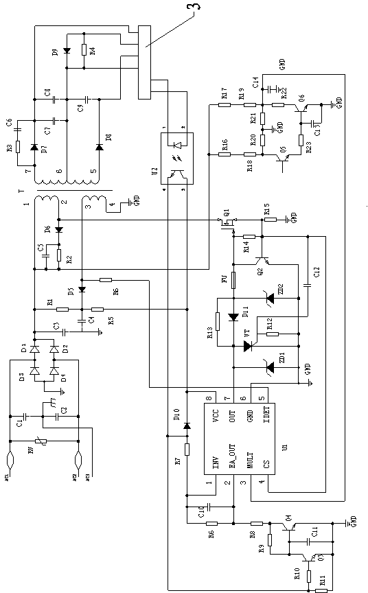
[0039] Examples such as figure 2 , image 3 As shown, an LED driving circuit includes a power supply circuit 1 , an output circuit 2 , a voltage stabilizing circuit 3 , an amplifying circuit 4 , a sampling circuit 5 , a driving control circuit 6 , a protection circuit 7 and a PFC correction circuit 8 .

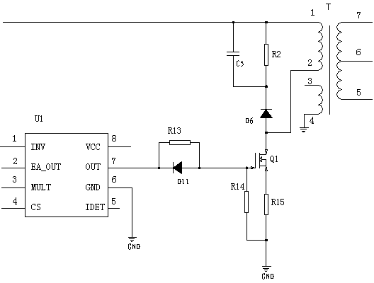
[0040] The power supply circuit 1 includes diode D1, diode D2, diode D3, diode D4, diode D5, diode D6, resistor R1, resistor R2, capacitor C1, capacitor C2, capacitor C3, capacitor C4, capacitor C5 and switching transformer T, diode D1, The rectifier bridge composed of diode D2, diode D3, and diode D4, the switching transformer T has a first primary coil, a second primary coil and a secondary coil, the capacitor C3 is connected between the positive pole of the rectifier bridge and the ground, and one end of the resistor R1 is connected to the rectifier The positive pole of the bridge, the other end of the resistor R1 is connected to one end of the capacitor C4, the negative ...


PUM


Abstract

The invention relates to an LED driving circuit. A protective circuit comprises an audion Q2. A collector of the audion Q2 is connected with a grid electrode of a field effect transistor Q1. A base electrode of the audion Q2 is connected with a source electrode of the field effect transistor Q1. An emission electrode of the audion Q2 is connected with the ground. The protective circuit comprises a resistor R12, a capacitor C12 and a thyristor VT. An anode of the thyristor VT is connected with a driving output end of a driving chip U1. A cathode of the thyristor VT is connected with the ground. A gate electrode of the thyristor VT is connected with one end of the resistor R12 and one end of the capacitor C12. The other end of the resistor R12 is connected with the ground. The other end of the capacitor C12 is connected with the source electrode of the field effect transistor Q1. After the field effect transistor Q1 is subjected to breakdown, the audion Q2 is subjected to saturation quickly, shorting circuit the ground of the collector of the audion Q2 is carried out, the driving chip U1 is protected, the upper end of a current limiting resistor R15 generates high voltages, and meanwhile the high voltages are added to the gate electrode of the thyristor VT through the capacitor C12, so that the gate electrode is connected, anode voltages of the thyristor VT are lowered to 0V, so that the driving chip U1 is protected, the driving chip U1 is effectively protected, and multiple protection is achieved.

Description

technical field [0001] The invention relates to a power supply circuit, in particular to an LED drive circuit suitable for the power supply of LED lighting lamps, and belongs to the field of electronic technology. Background technique [0002] At present, the traditional LED lighting driving circuit includes a power supply circuit 1, an output circuit 2, a voltage stabilizing circuit 3, an amplifying circuit 4, a sampling circuit 5, a driving control circuit 6 and a PFC correction circuit 8, such as figure 1 As shown, the driving control circuit 6 includes a driving chip U1, a field effect transistor Q1, and the pin 7 of the driving chip U1, that is, the diode D11 connected to the gate of the field effect transistor Q1 at the drive output terminal, and the source of the field effect transistor Q1 The resistor R15 is grounded, the diode D11 is connected in parallel with the resistor R13, the gate of the field effect transistor Q1 is grounded through the resistor R14, the drai...

Claims


Application Information

Patent Timeline
Patent Type & Authority Applications(China)
IPC IPC(8): H05B37/02
Inventor 李建军刘祖社邱纯勇
Owner 潍坊晶兰电源技术有限公司
Why Eureka
Try Eureka