Recirculating loop for fuel cell

A fuel cell stack, recycling technology, applied in fuel cells, fuel cell additives, circuits, etc., can solve problems such as huge

Active Publication Date: 2013-10-09
MICHELIN & CO CIE GEN DES ESTAB MICHELIN
View PDF7 Cites 7 Cited by
  • Summary
  • Abstract
  • Description
  • Claims
  • Application Information

AI Technical Summary

Problems solved by technology

[0004] The object of the present invention is to succeed in providing a close control of gas recirculation and purge, or venting to atmosphere, both of which are nece

Method used


Image

  • Recirculating loop for fuel cell
  • Recirculating loop for fuel cell
  • Recirculating loop for fuel cell

Examples


Embodiment Construction

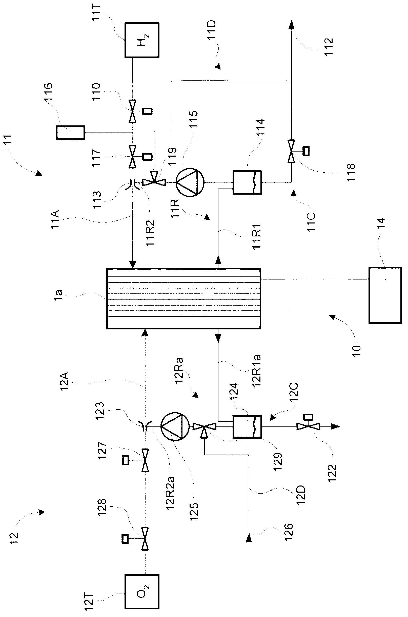
[0021] figure 1 A fuel cell stack 1 a of the type having an electrolyte in the form of a polymer membrane is shown (ie of the PEFC (polymer electrolyte fuel cell) or PEM (proton exchange membrane) type). The fuel cell stack 1 a is supplied with two gases, a fuel (hydrogen stored or generated on board the vehicle) and an oxidant (in this example, pure oxygen), whose gas is supplied to the electrodes of the electrochemical cells. The power loader 14 is connected to the fuel cell stack 1 a through the power line 10 . To simplify things, figure 1 Only gas line parts are shown for understanding the invention.

[0022] Description of the anode circuit:

[0023] show on figure 1 The arrangement in includes a fuel gas supply line 11 on the anode side. Pure hydrogen (H 2 ) tank 11T is visible, the pure hydrogen (H 2 ) tank 11T is connected to the inlet of the anode circuit of the fuel cell stack 1a by a supply line passing through the shut-off valve 110, then through the press...


PUM


Abstract

The invention relates to a recirculating loop (11R or 12Ra) for a gas circuit of a fuel cell (1a), which recirculating loop forms a connection duct beginning at the outlet of one of the two anode or cathode circuits of the fuel cell stack (1) and terminating on one of the two supply circuits, either on the fuel-gas supply duct (11A) or on the oxidant-gas supply duct (12A). The recirculating loop recirculates the gas contained in the anode or cathode circuits of the fuel cell, said recirculating loop comprising a pump (115 or 125) for recirculating said gas. The recirculating loop comprises a multi-way valve (119 or 129) that divides the loop into a first section (11R1 or 12R1) and a second section (11R2a or 12R2a), said multi-way valve having: a first stable operating position which establishes continuity between the first and second sections of the loop; and a second stable operating position which simultaneously interrupts the continuity between the first and second sections of the recirculating loop and brings said recirculating loop into contact with the atmosphere, by moving the multi-way valve.

Description

technical field [0001] The present invention relates to fuel cell stacks, more particularly, but not exclusively, to fuel cell stacks of the type having an electrolyte in the form of a polymer membrane (ie PEFC (Polymer Electrolyte Fuel Cell)). Background technique [0002] Fuel cell stacks are known to be able to generate electrical energy directly by electrochemical redox reactions starting from hydrogen (fuel) and oxygen (oxidant), without going through a mechanical energy conversion step. The technology seems promising, especially for motor vehicle applications. A fuel cell stack typically includes a series of individual parts, each consisting essentially of an anode and a cathode separated by a polymer membrane that enables the passage of ions from the anode to the cathode. In the case of a "dead end" line, that is, the line is not normally open at ambient conditions, which is usually the case for the anode circuit, and also for the cathode of a battery intended to ope...

Claims


Application Information

Patent Timeline
IPC IPC(8): H01M8/04
CPCH01M2008/1095H01M8/0441H01M8/04402H01M8/04164H01M8/04231H01M8/04514H01M8/04097Y02E60/50H01M8/04753H01M8/04559H01M8/04589H01M8/04761
Inventor G·帕加内利
Owner MICHELIN & CO CIE GEN DES ESTAB MICHELIN
Why Eureka
Try Eureka