Strongly magnetic vortex sorter

An eddy current separation and strong magnetic technology, applied in the fields of magnetic separation, solid separation, chemical instruments and methods, etc., can solve the problems of the separation material spilling on the ground, affecting the working environment, etc., and achieve the effect of reducing the size and increasing the size.

Inactive Publication Date: 2013-10-16
TAIZHOU WEIBO ENVIRONMENTAL PROTECTION EQUIP TECH
View PDF6 Cites 10 Cited by
  • Summary
  • Abstract
  • Description
  • Claims
  • Application Information

AI Technical Summary

Problems solved by technology

In the above-mentioned structure, the discharge port is provided with discharge port 1 and discharge port 2, and the discharge port 1 and discharge port 2 have a distance. When discharging, the sorting material sometimes falls on the ground, affecting working environment

Method used


Image

  • Strongly magnetic vortex sorter
  • Strongly magnetic vortex sorter
  • Strongly magnetic vortex sorter

Examples


Embodiment 1

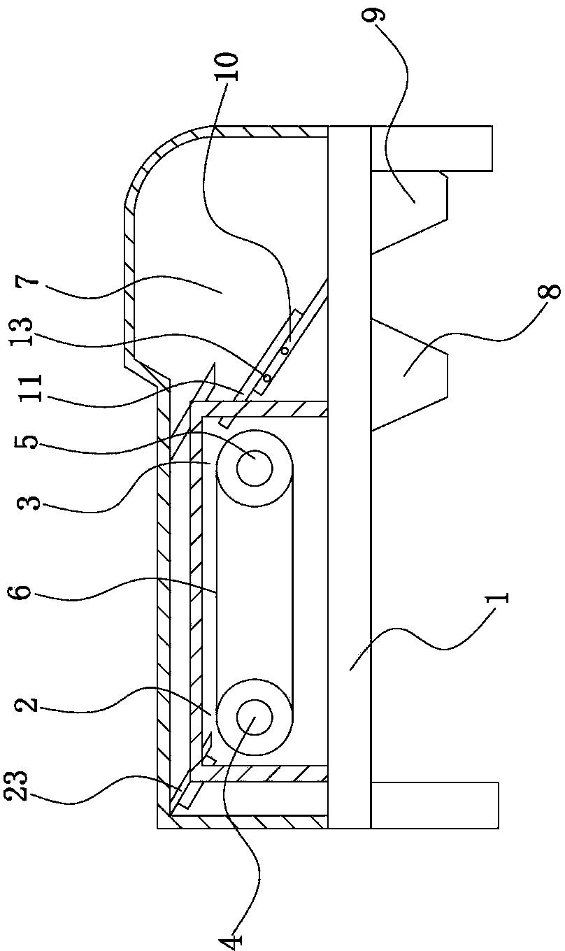
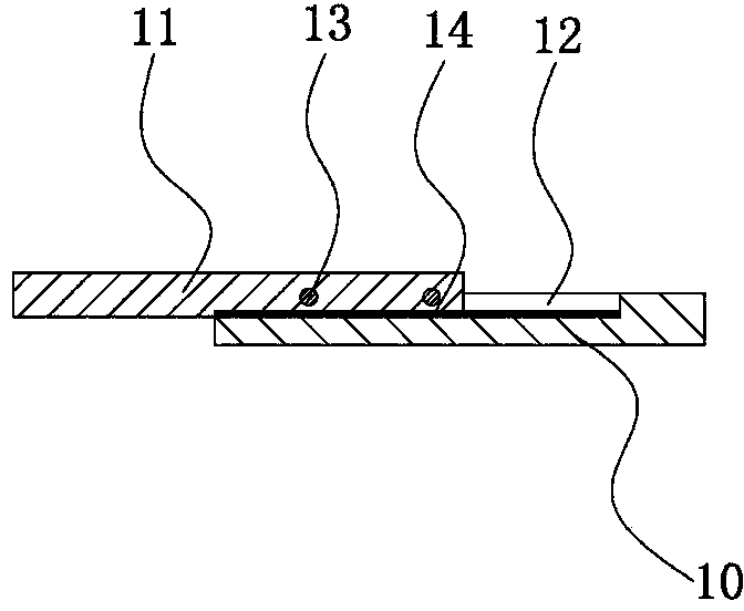
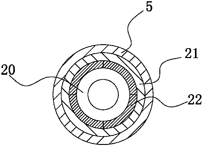
[0025] Such as figure 1 , figure 2 , image 3 with Figure 4 As shown, the strong magnetic eddy current separator is mainly composed of a base 1, on which an inlet 2 and an outlet 3 are arranged, and on the base 1 at the inlet 2, a motor is arranged. The rotating shaft 4 is provided with a rotating roller 5 parallel to the rotating shaft 4 on the base 1 at the outlet 3, and a conveyor belt 6 is connected between the rotating shaft 4 and the rotating roller 5. The seat 1 is also provided with a material distribution chamber 7, and the material distribution chamber 7 is obliquely provided with a discharge plate 10 that separates the material distribution chamber 7 into the material distribution port 1 8 and the material distribution port 2 9. The inclination direction of the discharge plate 10 is located in the tangential direction of the discharge port end of the above-mentioned conveyor belt 6. On the discharge plate 10 near the end of the discharge port 3, there is a slid...

Embodiment 2

[0029] Such as figure 1 or Figure 5 As shown, the structure of this implementation is basically the same as that of Embodiment 1, the difference is that the adjustment device is mainly provided with a rectangular partition plate 15 on the discharge plate, and the tangent line along the discharge port end of the conveyor belt 6 on the rectangular partition plate 15 The direction is provided with several strip holes, and the rectangular partition plate 15 is fixed on the above-mentioned discharge plate 10 through the above-mentioned strip holes by bolts; the strip hole includes a strip hole one 16, Strip hole two 17, strip hole three 18 and strip hole four 19, described strip hole one 16 and strip hole two 17 are parallel to each other, and the strip hole three 18 and strip hole one 16 are arranged in a straight line , the strip hole four 19 and the strip hole two 17 are arranged in a straight line.


PUM


Abstract

The invention provides a strongly magnetic vortex sorter, belongs to the technical field of waste recycling mechanical equipment, and solves the problem that in sorting process of the conventional strongly magnetic vortex sorter, a material sometimes scatters onto the ground. The strongly magnetic vortex sorter comprises a pedestal, wherein a feed port and a discharge port are formed on the pedestal; a conveyor belt is connected between a rotating shaft and a rotating roll; a sorting chamber is formed on the pedestal at the discharge port end; a discharging plate for partitioning the sorting chamber into a sorting port 1 and a sorting port 2 is arranged inside the sorting chamber in an inclined way; the inclining direction of the discharging plate is in the tangential direction of the discharge port end of the conveyor belt; a regulating device capable of synchronously regulating the discharging amounts of the sorting port 1 and the sorting port 2 is arranged on the discharging plate near the discharge port end in a sliding way. The strongly magnetic vortex sorter reduces the size of the sorting port 1 as well as increases the size of the sorting port 2; and when a rectangular regulating plate moves downwards in an inclining way by fitting the discharging plate, the size of the sorting port 1 is increased and the size of the sorting port 2 is reduced.

Description

technical field [0001] The invention belongs to the technical field of waste recycling mechanical equipment, and relates to a strong magnetic eddy current separator. Background technique [0002] With the continuous deepening of industrialized society and the improvement of people's living standards, more and more garbage and waste materials are discharged in production and life. For a long time, people have mainly adopted simple stacking, landfill, and incineration methods for garbage disposal, which not only occupy a large amount of cultivated land, but also cause secondary pollution, pollute the environment and cause ecological disasters. [0003] In the current sorting process of solid waste such as waste cars, household appliances, refrigerators, washing machines, circuit boards, industrial waste and other crushed materials, in order to separate non-ferrous metals from non-metallic and ferrous metals. The commonly used methods are: manual sorting, wind sorting, gravity...

Claims


Application Information

Patent Timeline
Patent Type & Authority Applications(China)
IPC IPC(8): B03C1/23
Inventor 童加增
Owner TAIZHOU WEIBO ENVIRONMENTAL PROTECTION EQUIP TECH
Why Eureka
Try Eureka