
Suspension bridge cable bent tower beam non-support construction method

A construction method and a technology without supports, which are applied in the direction of bridges, bridge construction, erection/assembly of bridges, etc., can solve the problems of not providing beam support structures and methods, increased construction safety risks, and long periods of support erection. The effect of increased construction cost, long construction period and saving construction time

Inactive Publication Date: 2013-10-16
ROAD & BRIDGE INT +1
View PDF6 Cites 17 Cited by
  • Summary
  • Abstract
  • Description
  • Claims
  • Application Information

AI Technical Summary

Problems solved by technology

[0003] 1. The bracket erection period is long, which affects the construction period;
[0004] 2. As the height of the tower increases, the position of the beam increases, the height of the bracket increases accordingly, and the risk of construction safety increases;
[0005] 3. After the bracket is erected, it needs to be preloaded, which is time-consuming and laborious
But there is a problem: during the construction of the beam, the formwork system, including the bottom formwork, side formwork, top formwork, etc., as well as the binding of steel bars, the installation of prestressed pipes, etc., all require structural support, and this scheme only provides a suspended The construction platform does not involve the construction of the beam, nor does it provide the support structure and method in the construction of the beam, which makes the specific implementation of the plan impossible

Method used


Image

  • Suspension bridge cable bent tower beam non-support construction method
  • Suspension bridge cable bent tower beam non-support construction method
  • Suspension bridge cable bent tower beam non-support construction method

Examples


Embodiment Construction

[0036] The method and construction process of the present invention will be described in detail below in conjunction with the accompanying drawings through the embodiments.

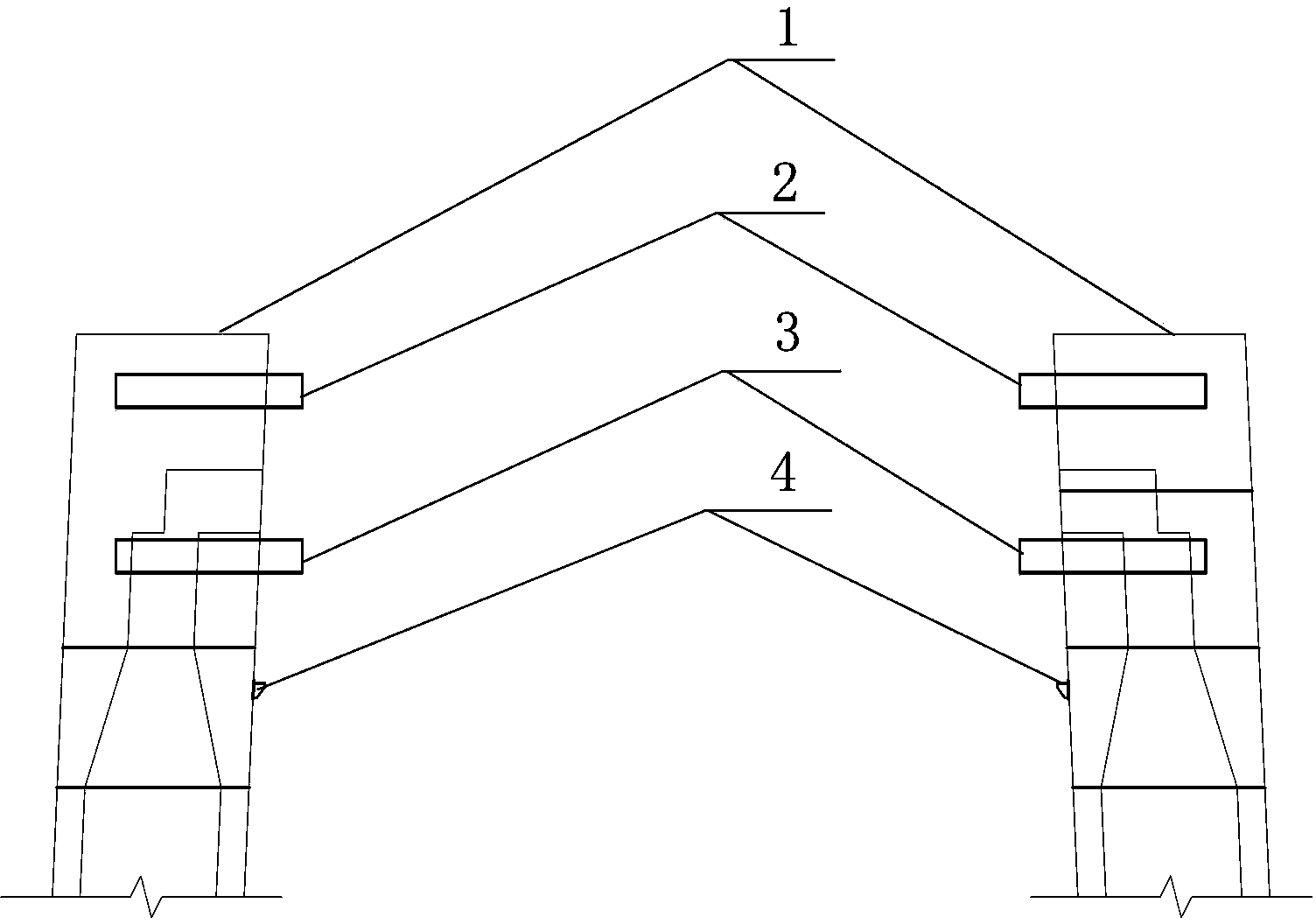
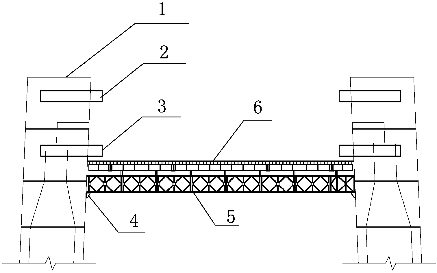
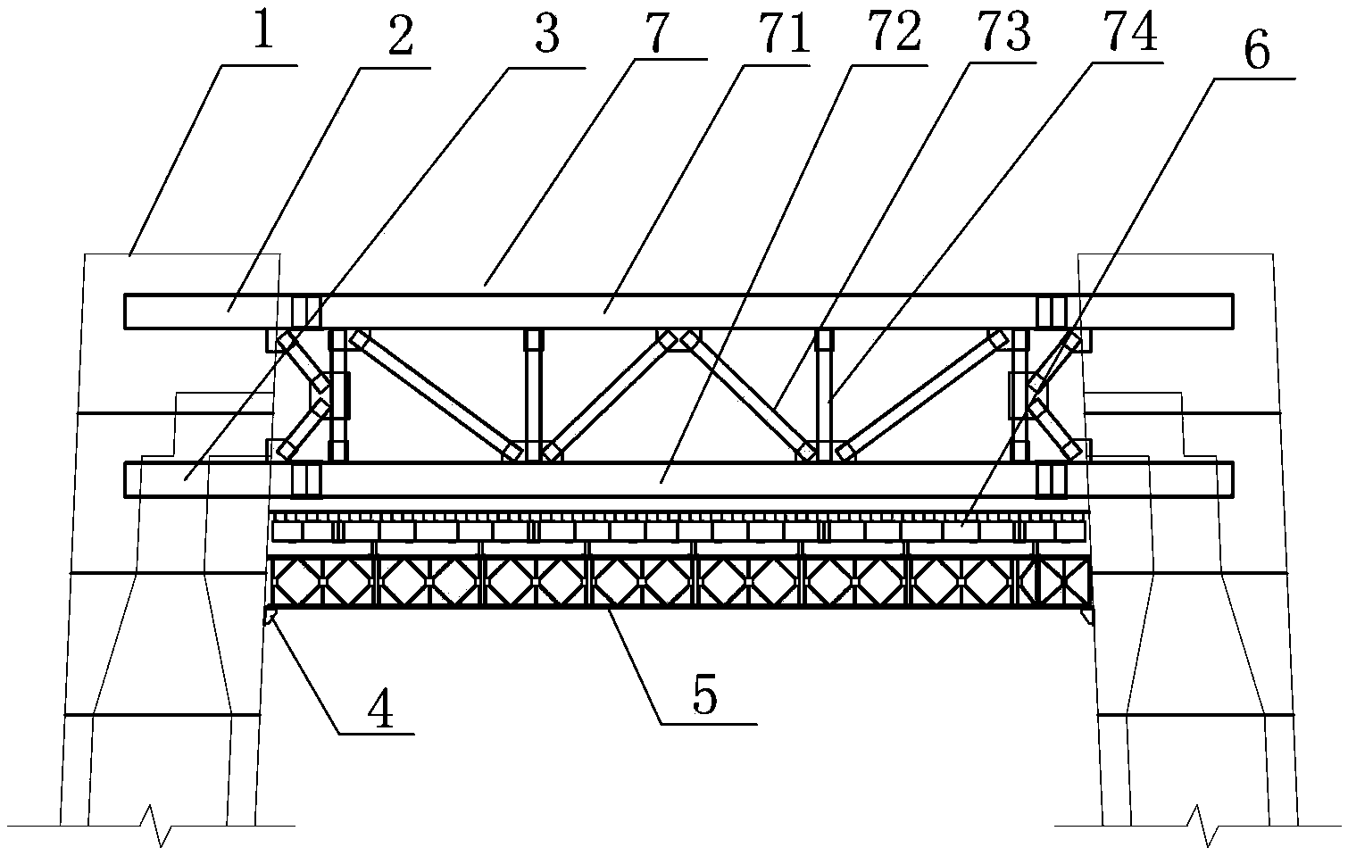
[0037] Such as figure 1 As shown, in the construction process of the tower column 1, when the tower column 1 is constructed to the predetermined position of the beam, along the opposite direction of the two tower columns, the truss connector is pre-embedded in the tower column 1, and the truss connector It includes an upper connecting piece 2 and a lower connecting piece 3, and the heights of the upper connecting piece 2 and the lower connecting piece 3 are respectively consistent with the heights of the bottom plate and the top plate of the predetermined beam; the lower connecting piece is located on the two tower columns Corbel 4 is installed below 3. According to construction requirements, it is more appropriate for the corbel 4 to be located 3-4m below the lower connector.

[0038] Such as figure ...


PUM


Abstract

The invention relates to a suspension bridge cable bent tower beam non-support construction method. The method includes the steps that when tower columns of a cable bent tower are constructed to the position where a beam is preset, truss connecting pieces are pre-buried in the tower columns, and brackets are installed below the connecting pieces; the brackets are used for supporting, an operating platform is erected, and assembly of soffit formworks of the beam is completed on the operating platform; a steel truss is welded, the two ends of the steel truss are welded with the truss connecting pieces on the two tower columns respectively, a suspension system is installed on the steel truss, and the suspension system is used for lifting the soffit formworks to the bottom surface of a base plate of the beam for elevating; then beam base plate rebar binding, base plate concrete pouring, beam web rebar binding, web concrete pouring, beam crown plate rebar binding and crown plate concrete pouring are sequentially conducted, and beam pouring construction is completed. The steel truss is used as a temporary supporting and load-carrying structure in the construction process, and after the construction is completed, the steel truss becomes a part of the beam.

Description

technical field [0001] The invention relates to a construction method for a cable tower beam of a long-span suspension bridge, belonging to the field of bridge construction. Background technique [0002] Suspension bridges are widely used in the field of bridge construction due to their advantages such as strong spanning ability and no impact on navigation under the bridge. The suspension bridge supports the suspension cables through the cable towers. Each cable tower includes two tower columns. In order to maintain the strength and stability of the cable tower, the two tower columns should be connected by a beam, and the beam is set at a certain height of the tower column. At present, floor supports are generally used in the construction of long-span suspension bridge cable tower beams, such as full hall supports or column supports. The floor support is to use steel pipes and other materials to build supports from the ground up to the beam construction position, build a co...

Claims


Application Information

Patent Timeline
Patent Type & Authority Applications(China)
IPC IPC(8): E01D21/00
Inventor 刘华宋冰
Owner ROAD & BRIDGE INT
Learn More