Typified form of ribbed floors
A technology for shaping templates and templates, which is applied in the field preparation of formwork/formwork/work frames, building components, construction, etc., and can solve problems such as high cost, non-returnable utilization, and reduction of economic indicators of ribbed beam floors. , to achieve the effect of reducing production costs, increasing turnover rate, and reducing rental prices
- Summary
- Abstract
- Description
- Claims
- Application Information
AI Technical Summary
Problems solved by technology
Method used
Image
Examples
Embodiment 1
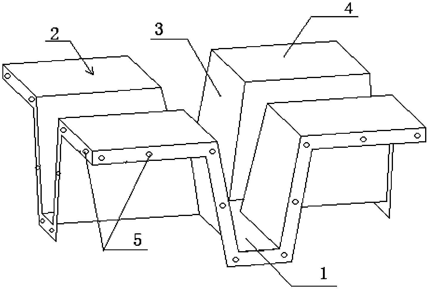
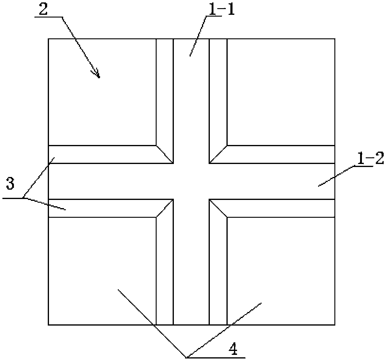
[0063] Such as figure 1 and 2 As shown, a spreader template includes two support arms 1 and four tire molds 2, the support arms 1 are connected to the tire molds 2, a cross-shaped intersection is formed between the support arms 1, and the two support arms Respectively a vertical support arm 1-1 and a horizontal support arm 1-2; the tire mold has a membrane top plate 4 and a membrane wall 3, and the membrane wall 3 is connected to the support arm 1; the membrane top plate 4 and the side of the membrane wall 3 are provided with connecting flange 5.
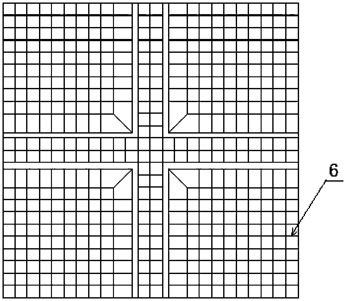
[0064] Such as image 3 As shown, in order to improve the strength of the template, stiffeners 6 are provided on the inner side of the tire membrane 2 and the support arm 1, and the stiffeners 6 are longitudinal or transverse protrusions.
Embodiment 2
[0066] Such as Figure 4 , 5 and Figure 6 As shown, a side mold includes two support arms 1 and two tire molds 2, the support arms 1 are connected to the tire mold 2, and the two support arms 1 are respectively a vertical support arm 1-1 and a horizontal support arm 1 -2, forming a T-shaped intersection between them; the tire mold 2 has a membrane top plate 4 and a membrane wall 3, and the membrane wall 3 is connected to the support arm 1; the membrane top plate 4 and the membrane A connecting flange 5 is provided on the side of the wall 3 .
[0067] Such as Figure 7 As shown, in order to improve the strength of the template, stiffeners 6 are provided on the inner side of the tire membrane 2 and the support arm 1, and the stiffeners 6 are longitudinal or transverse protrusions.
Embodiment 3
[0069] Such as Figure 8 and Figure 9 As shown, a corner mold includes two support arms 1 and a tire mold 2, the support arm 1 is connected to the tire mold 2, and the two support arms 1 are respectively a vertical support arm 1-1 and a horizontal support arm 1- 2, forming an L-shaped intersection between them; the tire mold 2 has a membrane top plate 4 and a membrane wall 3, and the membrane wall 3 is connected to the support arm 1; the membrane top plate 4 and the membrane wall The side of 3 is provided with connecting flange 5.
[0070] Such as Figure 10 As shown, in order to improve the strength of the template, stiffeners 6 are provided on the inner side of the tire membrane 2 and the support arm 1, and the stiffeners 6 are longitudinal or transverse protrusions.
PUM
 Abstract
Description
Claims
Application Information
 - R&D
- Intellectual Property
- Life Sciences
- Materials
- Tech Scout
- Unparalleled Data Quality
- Higher Quality Content
- 60% Fewer Hallucinations
Browse by: Latest US Patents, China's latest patents, Technical Efficacy Thesaurus, Application Domain, Technology Topic, Popular Technical Reports.
© 2025 PatSnap. All rights reserved.Legal|Privacy policy|Modern Slavery Act Transparency Statement|Sitemap|About US| Contact US: help@patsnap.com


