A diesel engine cooling system

A cooling system and diesel engine technology, applied in the direction of engine cooling, mechanical equipment, engine components, etc., can solve the problems of increased difficulty in cooling system design and layout, and increase the difficulty of assembly, so as to reduce the difficulty of layout, reduce the difficulty of layout, The effect of balanced weight distribution

Active Publication Date: 2016-05-11
ANHUI JIANGHUAI AUTOMOBILE GRP CORP LTD
View PDF8 Cites 2 Cited by
  • Summary
  • Abstract
  • Description
  • Claims
  • Application Information

AI Technical Summary

Problems solved by technology

[0004] Such an arrangement needs to set up a water inlet and a water outlet respectively on the front face of the cylinder block and the cylinder head of the engine, and the positions where both need to be arranged are the places where the engine parts are the most, which adds a lot to the design and arrangement of the cooling system. The difficulty, but also increased the difficulty of post-assembly

Method used


Image

  • A diesel engine cooling system
  • A diesel engine cooling system
  • A diesel engine cooling system

Examples


Embodiment Construction

[0027] The technical solution of the present invention will be described in detail below through specific examples. It should be understood that the following examples are exemplary only, and can only be used to explain and illustrate the technical solution of the present invention, and cannot be interpreted as a technical solution of the present invention. Program limitations.

[0028] In the technical solution of the present invention, the cylinder block cooling water channel and the cylinder head cooling water channel of the engine are all prior art, because there are many changes in the cylinder block cooling water channel and the cylinder head cooling water channel in the prior art, but, As long as there are cylinder block cooling water passages and cylinder head cooling water passages, the technical solution of the present application can be applied.

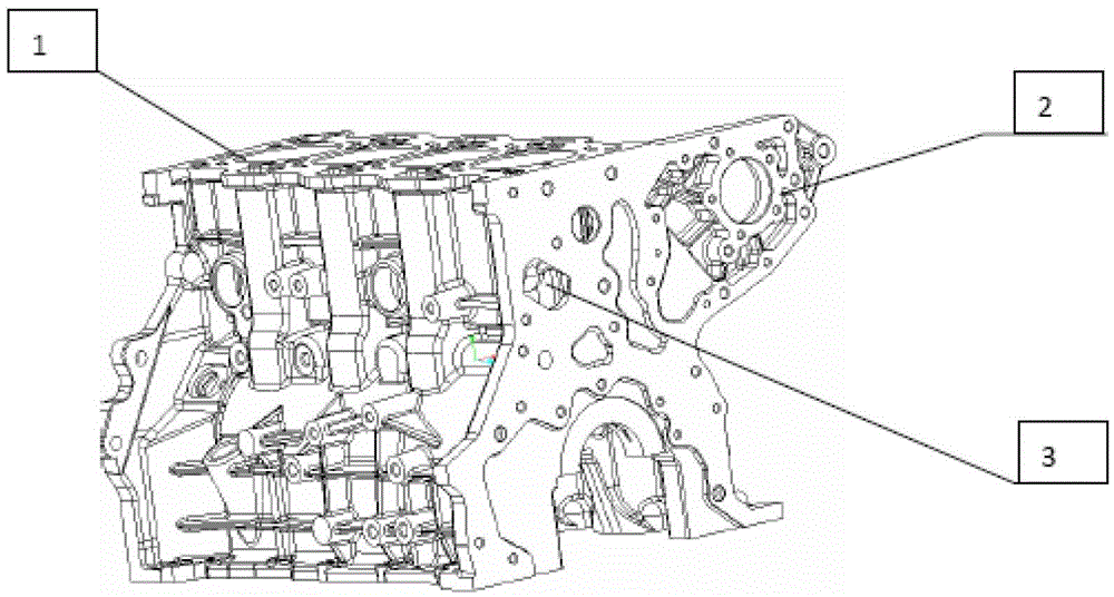
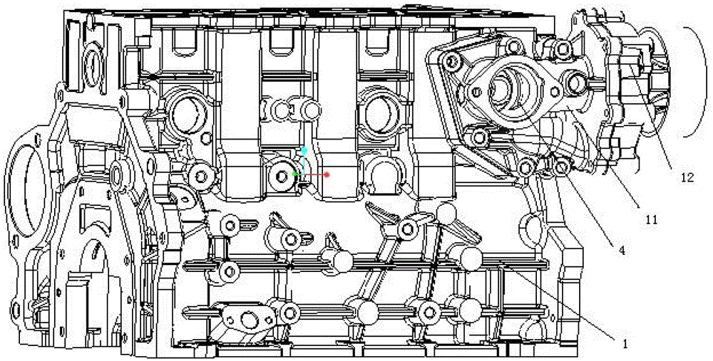
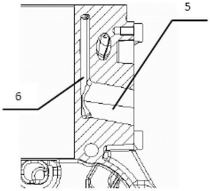
[0029] Such as Figure 2 to Figure 5 As shown, the engine coolant enters the thermostat valve seat water inlet channel ...


PUM


Abstract

The invention relates to a cooling system of a diesel engine. The cooling system of the diesel engine comprises a water inlet channel, a cylinder body cooling water channel, a cylinder cover cooling water channel and a water outlet channel, wherein the water inlet channel is composed of a water inlet formed in the side surface of a cylinder body, a thermostat valve seat and a water pump outlet, and the water outlet channel is composed of a water outlet formed in the side surface of the cylinder body and a heat dissipation device. A water inlet pipe and a water outlet pipe of an engine are moved to the air inlet side or the air outlet side of a motor cylinder body. Due to the fact that the selective space of the arrangement in the position of the air inlet side or the air outlet side is larger, the difficulty of the arrangement is reduced, and the overall arrangement and the post installation of the engine are facilitated.

Description

technical field [0001] The invention belongs to the field of diesel engines, in particular to a diesel engine cooling system. Background technique [0002] The cooling system of the engine sends the coolant to the parts that need to be cooled and each cooler through the water pump, and the engine is cooled by heat exchange. re-enters each cooler, thereby enabling circulation. Such as figure 1 As shown, in the prior art, the direction of the cooling liquid all enters the engine block 1 and the cylinder head from the engine water inlet 3 of the engine front face 2, and enters the vehicle radiator from the engine cylinder head after cooling. [0003] The main feature of the engine cooling system with this structure is that it is necessary to arrange water inlets and outlets on the front end of the engine 2 and the cylinder head respectively, and the two places are the places where the most parts of the engine are arranged, and the front end of the engine needs to arrange fans...

Claims


Application Information

Patent Timeline
Patent Type & Authority Patents(China)
IPC IPC(8): F02F1/10F01P11/00
Inventor 黄凯孟祥山高巧喻昆王宏大陈晓东杨洪震赵炳雄
Owner ANHUI JIANGHUAI AUTOMOBILE GRP CORP LTD
Why Eureka
Try Eureka