Combined type combustor

A combined, burner technology, applied in the directions of burners, lighting and heating equipment, can solve the problems of difficult furnace heating and flameless combustion, and achieve the effect of enhancing flexibility, strong adaptability, and solving furnace heating difficulties.

Active Publication Date: 2013-10-16
HUAZHONG UNIV OF SCI & TECH
View PDF10 Cites 0 Cited by
  • Summary
  • Abstract
  • Description
  • Claims
  • Application Information

AI Technical Summary

Problems solved by technology

[0005] The object of the present invention is to provide a combined burner, through the switching control of the oxidant sprayed from the oxidant nozzles arranged on the top of the furnace and located around its periphery, respectively to achieve central swirl combustion or flameless combustion, or to realize central swirl combustion at the same time. Flow combustion and flameless combustion, so as to realize the combined combustion that satisfies the switching between central swirling combustion and flameless combustion of the boiler at the same time, and solves the difficulty in raising the temperature of the furnace in the early stage of current flameless combustion and the inability to achieve flameless only through a single structure Combustion deficiencies, while achieving versatility in a variety of combinations of combustion

Method used


Image

  • Combined type combustor
  • Combined type combustor
  • Combined type combustor

Examples


Embodiment Construction

[0030] In order to make the object, technical solution and advantages of the present invention clearer, the present invention will be further described in detail below in conjunction with the accompanying drawings and embodiments. It should be understood that the specific embodiments described here are only used to explain the present invention, not to limit the present invention. In addition, the technical features involved in the various embodiments of the present invention described below may be combined with each other as long as they do not constitute conflicts with each other.

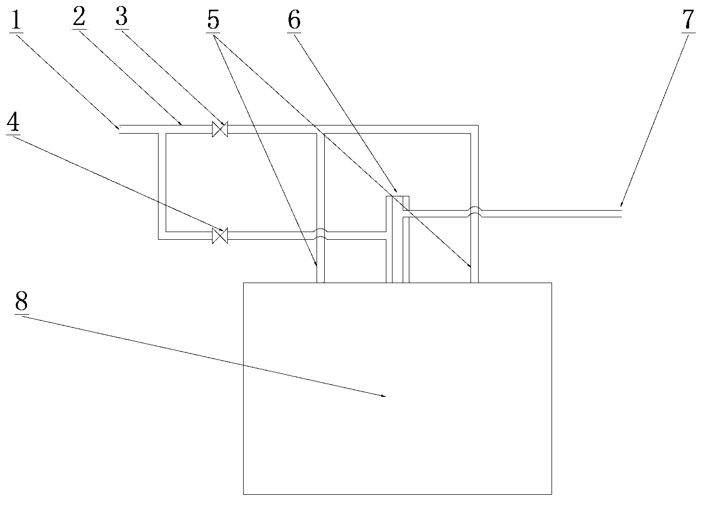
[0031] figure 1 It is a structural schematic diagram of a flameless combustion combined burner according to an embodiment of the present invention. The combined burner includes a central swirl nozzle 6, a distributed oxidant inlet nozzle 5 (flameless combustion nozzle), and a switching pipeline 2.

[0032]The central swirl nozzle 6 has an inlet port and an outlet port, which is arranged on the ...


PUM


Abstract

The invention discloses a flameless combustion combined type combustor which comprises a central swirl nozzle, oxidant nozzles and a switch pipeline, wherein the central swirl nozzle is arranged at the top of a combustion chamber and is communicated with the combustion chamber through an outlet end; an inlet end comprises a fuel inlet end and an oxidant inlet end; fuel and an oxidant enter the central swirl nozzle and are ejected into the interior of a furnace chamber through the corresponding inlet ends respectively; the oxidant nozzles are uniformly arranged at the top of the furnace chamber, communicated with the furnace chamber and uniformly and circularly arranged on the periphery of the central swirl nozzle which is taken as the center; the switch pipeline comprises a first branch pipe and a second branch pipe; valves used for communicating and closing the pipeline are arranged on the two branch pipes respectively; by the aid of the switching control to the valves, the oxidant is ejected into the furnace chamber from the central swirl nozzle and/or the oxidant nozzles, and central swirl combustion and/or flameless combustion are/is realized. According to the combined type combustor, different combustion manners such as the central swirl combustion, the flameless combustion and the like of the combustion chamber can be realized at the same time, and the competence of the combustion chamber for regulating different combustion manners can be improved.

Description

technical field [0001] The invention relates to a burner, which is suitable for the fields of coal-fired and gas-fired boilers in power stations and industrial coal-fired and gas-fired boilers. Background technique [0002] Improving the combustion efficiency of fossil fuels and reducing pollutant emissions during combustion have always been an important research direction in the field of energy utilization. Flameless combustion is a spatially distributed combustion mode in which reactants are diluted in a low-oxygen atmosphere. Flameless combustion originated from Weinberg's super-enthalpy idea. Due to the dilution and preheating of the reactants by the high-temperature circulating flue gas, the temperature of the reactants is increased and the oxygen concentration in the reaction zone is reduced. Once the temperature of the reactants reaches the ignition point, a slow combustion occurs. oxidation reaction. A large amount of flue gas circulation provides a high-temperatur...

Claims


Application Information

Patent Timeline
Patent Type & Authority Applications(China)
IPC IPC(8): F23D17/00
Inventor 柳朝晖黄仕鑫王林
Owner HUAZHONG UNIV OF SCI & TECH
Why Eureka
Try Eureka