Expansive force terminal strain clamp of composite core aluminum-stranded conductor

A technology of tension-resistant clamps and aluminum stranded wires, applied in the direction of adjusting/maintaining mechanical tension, which can solve the problems of small contact surface, many edges and corners on the outside of the device, loss of power supply facilities, etc., to achieve stable radial pressure, reduce discharge phenomenon, The effect of increasing friction

Inactive Publication Date: 2013-10-16
蔡威
View PDF0 Cites 1 Cited by
  • Summary
  • Abstract
  • Description
  • Claims
  • Application Information

AI Technical Summary

Problems solved by technology

[0002] At present, there are mainly three kinds of devices for fixing and clamping the steel-reinforced aluminum stranded wire in domestic transmission line connection clamps. One is wire plugging, the contact surface is small and the plugging is not strong, and the wires are prone to heat; the other is aluminum tube hydraulic pressure. When installing, the wires at both ends are inserted into the aluminum tube, and then pressurized with a hydraulic tool, but the contact surface is small and the grip is not strong; The impact force changes the metallographic phase, the mechanical strength is reduced, and the explosion is not safe
Therefore, the current connecting wire clips used on domestic transmission lines have defects such as inconvenient installation, small contact surface, easy heating of wires, insufficient grip strength, and reduced mechanical strength, and cannot be used for fixing and clamping connections of new material composite core aluminum stranded wires.
The utility model patent with the patent number of 2007200347845 overcomes some of the above-mentioned problems technically, especially for the clamp...

Method used


Image

  • Expansive force terminal strain clamp of composite core aluminum-stranded conductor
  • Expansive force terminal strain clamp of composite core aluminum-stranded conductor
  • Expansive force terminal strain clamp of composite core aluminum-stranded conductor

Examples


Embodiment approach

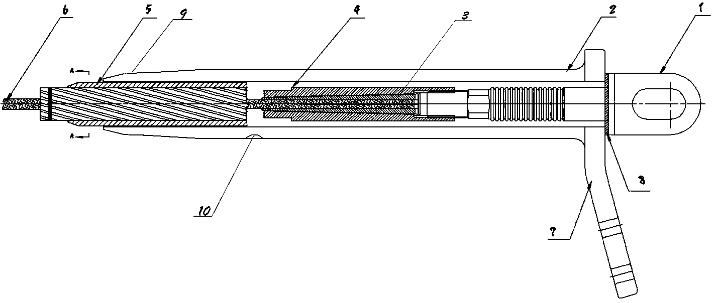
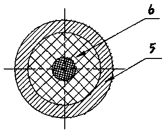
[0018] In the implementation mode, the composite core aluminum stranded wire is inserted into the inner liner (5), and then passed through the tension sleeve (2), the outer layer of the composite core aluminum stranded wire is stripped to expose the wire core (6), and the wire The core (6) penetrates the tension jacket (4), and then penetrates the tension sandwich core (3), and the tension sandwich core (3) is placed in the tension jacket (4), and the spinning steel anchor ( The secondary thread of 1) is screwed to the tension jacket (4), radially pushes the tension sandwich (3), then pushes the spinning steel anchor (1) into the tension jacket (2), and It is screwed and fixed with the tension casing (2), and at the same time, the inner liner (5) is placed in the front end of the tension casing, and finally the crimping point (9) and the burst point (10) are squeezed and fixed.


PUM


Abstract

The invention relates to an expansive force terminal strain clamp of a composite core aluminum-stranded conductor. The strain clamp is composed of a spinning type steel anchor, a strain casing tube, a tension clamp core, a strain clamp sleeve, an inner liner tube, a lead core, a drainage board, a silica gel pad, a compressing point, and an exploding pressing point. The tension clamp core is sleeved in the strain clamp sleeve and is arranged at the middle section of the strain casing tube. The front end of the spinning type steel anchor is contacted with the strain clamp sleeve and is fixed with the strain casing tube by a threaded connecting way; and the silica gel pad is arranged at the joint position for sealing. The front end of the strain clamp sleeve is arranged at the exploding pressing point; the inner liner tube is arranged in the front end of the strain casing tube and is compressed and fixed by the compressing point. The advantages of the strain clamp are as follows: the streamline design of the drainage board enables a discharging phenomenon to be alleviated and thus the energy consumption is reduced; a peripheral line is arranged at the outer surface of the inner liner tube and thus the friction force between the inner liner tube and the strain casing tube is increased, thereby improving the stability; and because of arrangement of the compressing point, the tension clamp core can generate a stable radial pressure and generate great gripping power. Moreover, the provided strain clamp has the characteristics of simple structure, convenient installation, and obvious effect.

Description

technical field [0001] The invention relates to a fixing, clamping and connecting device for aluminum stranded wires of composite core power cables in high-voltage overhead transmission lines. Specifically, it discloses a novel tension-resistant clamp for expansion force terminals of aluminum stranded wires with composite cores. Background technique [0002] At present, there are mainly three kinds of devices for fixing and clamping the steel-reinforced aluminum stranded wire in domestic transmission line connection clamps. One is wire plugging, the contact surface is small and the plugging is not strong, and the wires are prone to heat; the other is aluminum tube hydraulic pressure. When installing, the wires at both ends are inserted into the aluminum tube, and then pressurized with a hydraulic tool, but the contact surface is small and the grip is not strong; The impact force changes the metallographic phase, the mechanical strength is reduced, and the explosion is not sa...

Claims


Application Information

Patent Timeline
IPC IPC(8): H02G7/02
Inventor 仝合泽邵浩仝紫诺朱满意蔡威
Owner 蔡威
Why Eureka
Try Eureka