Inverted wire-rewinding machine

A wire take-up and inverted technology, which is applied in the field of inverted wire take-up, can solve the problems of the push rod sleeve card group and the complex structure of the push rod sleeve, and achieve the effects of convenient and fast advancing and retreating, simple structure and fast action speed.

Inactive Publication Date: 2013-10-23
WUXI PINGSHENG SCI & TECH
View PDF8 Cites 3 Cited by
  • Summary
  • Abstract
  • Description
  • Claims
  • Application Information

AI Technical Summary

Problems solved by technology

[0003] The take-up stand of the existing inverted take-up machine is connected to the take-up pulley through a push rod sleeve, and the take-up pulley drives the take-up stand to rotate and take up the line. When replacing the

Method used


Image

  • Inverted wire-rewinding machine
  • Inverted wire-rewinding machine

Examples


Embodiment Construction

[0015] The present invention will be further described below in conjunction with specific drawings and embodiments.

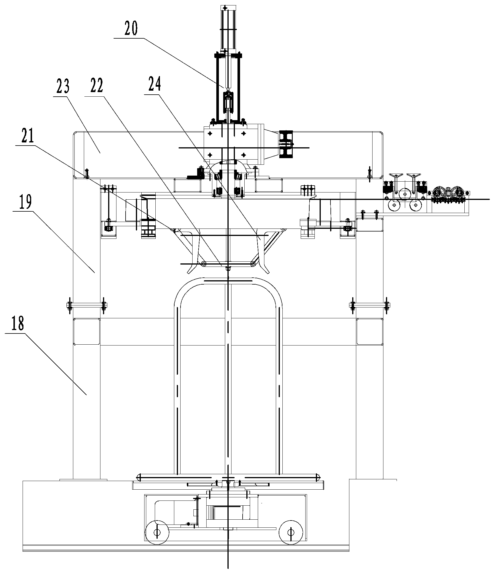
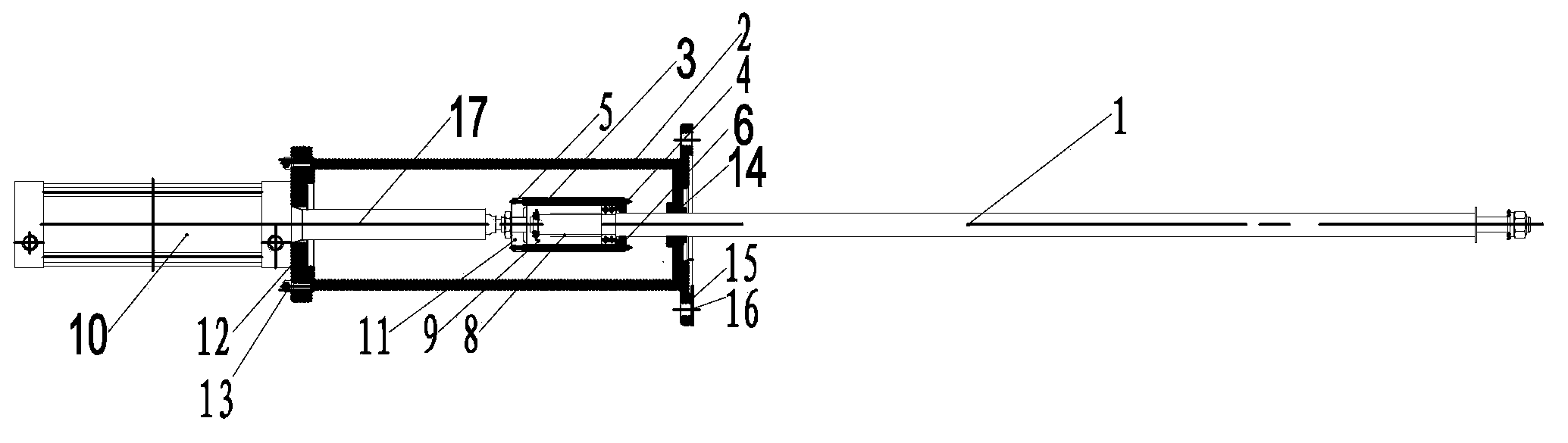
[0016] Such as figure 1 , figure 2 As shown, it includes straight tie rod 1, outer support sleeve 2, inner sleeve 3, third hexagon socket head screw 4, first hexagon socket head screw 5, inner lower cover 6, self-aligning ball bearing 7, support sleeve 8 , deep groove ball bearing 9, cylinder 10, internal threaded gland 11, flange 12, second hexagon socket head cap screw 13, sliding sleeve 14, connecting plate 15, connecting hole 16, push rod 17, lower frame 18, Upper frame 19, pneumatic thread accumulation mechanism 20, support 21, thread accumulation claw 22, first fence 23, winding reel 24, etc.

[0017] Such as figure 1 , figure 2 As shown, the present invention is an inverted wire take-up machine, comprising a lower frame 18, an upper frame 19 is fixedly mounted on the lower frame 18 by bolts, and a pneumatic wire accumulation mechanism is fixedly in...


PUM


Abstract

The invention belongs to the field of metal wire rod drawing technology, and specifically relates to an inverted wire-rewinding machine for winding metal wire rods. The inverted wire-rewinding machine comprises a lower machine frame, an upper machine frame is fixedly mounted on the lower machine frame through bolts, the center of the top of the upper machine frame is fixedly provided with a pneumatic wire accumulation mechanism, and the lower portion of the pneumatic wire accumulation mechanism passes through a top plate of the upper machine frame and extends into an inner cavity of the upper machine frame, the top plate of the upper machine frame is provided with a rolling-up winding drum at the bottom corresponding to a rod end at the lower portion of the pneumatic wire accumulation mechanism, a wire accumulation claw is hingedly mounted on a bracket arranged at the bottom of the rolling-up winding drum through bolts, and the lower end portion of a straight pull rod of the pneumatic wire accumulation mechanism is fixedly connected with a middle joint of the wire accumulation claw. The inverted wire-rewinding machine has simple and reasonable structure. One pneumatic wire accumulation mechanism is mounted on the top of the wire-rewinding machine, a push rod end of a cylinder of the pneumatic wire accumulation mechanism is connected to the straight pull rod, so that advancing and retreating of the straight pull rod can be conveniently and efficiently achieved; and because the action speed of the cylinder is fast, clamping group phenomenon of the straight pull rod cannot appear in a process of action.

Description

technical field [0001] The invention belongs to the technical field of metal wire drawing, in particular to an inverted wire take-up machine for winding metal wires. Background technique [0002] The wire take-up machine is used in conjunction with the wire drawing machine, and is a device that collects the metal wire that has been drawn into an ideal wire diameter. The wire take-up machine is suitable for wire-drawing and bundling of cold-drawn steel bars and cold-rolled ribbed steel bars. It can be used in conjunction with steel bar wire-drawing machines, steel bar cold-rolled ribbed machines, and steel bar extension machines. There is a special combination control cabinet, which is easy to operate. [0003] The take-up stand of the existing inverted take-up machine is connected to the take-up pulley through a push rod sleeve, and the take-up pulley drives the take-up stand to rotate and take up the line. When replacing the take-up stand, the take-up stand must be connect...

Claims


Application Information

Patent Timeline
IPC IPC(8): B21C47/04
Inventor 顾康建
Owner WUXI PINGSHENG SCI & TECH
Why Eureka
Try Eureka