
Laser axis calibrating method and laser processing device utilizing the same

A calibration method and laser technology, applied in laser welding equipment, metal processing equipment, manufacturing tools, etc., can solve problems such as optical axis deviation, achieve the effect of reducing calculation load and simple structure

Active Publication Date: 2013-10-23
TORAY ENG CO LTD
View PDF1 Cites 28 Cited by
  • Summary
  • Abstract
  • Description
  • Claims
  • Application Information

AI Technical Summary

Problems solved by technology

[0002] The laser light output from the laser oscillator tends to have its set optical axis change over time due to temperature changes of optical components arranged in the laser oscillator or on the optical path, or the optical axis may deviate due to aging of the device.

Method used


Image

  • Laser axis calibrating method and laser processing device utilizing the same
  • Laser axis calibrating method and laser processing device utilizing the same
  • Laser axis calibrating method and laser processing device utilizing the same

Examples


Embodiment Construction

[0085] Next, an embodiment of the present invention will be described with reference to the drawings.

[0086]

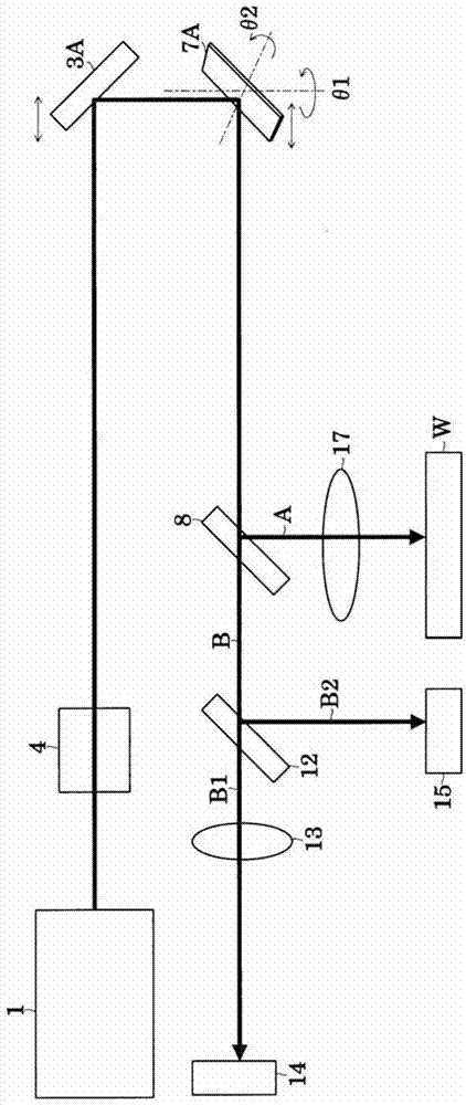
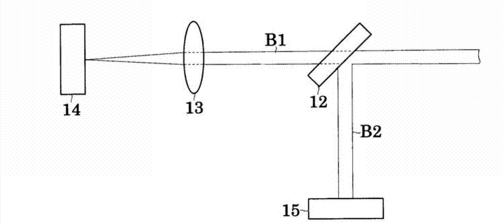
[0087] figure 1 A figure illustrating the principle of the laser optical axis calibration method of the present invention; figure 2 An enlarged view of the surrounding area of ​​the 2D semiconductor detector.

[0088] Such as figure 1 with figure 2 As shown, a beam expander 4 , a first mirror 3A, a second mirror 7A, a beam sampler 8 and a condenser lens 17 are disposed between the laser oscillator 1 and the workpiece W. In addition, a beam splitter 12 , a condensing lens 13 , and a two-dimensional semiconductor position detector 14 are disposed on the optical path of another laser beam B branched by the beam sampler 8 (hereinafter referred to as “measurement light B”). Here, the laser beam directed from the beam splitter 12 to the two-dimensional semiconductor position detector 14 serves as measurement light B1. Further, a two-dimensional semiconductor posi...


PUM


Abstract

The present invention provides a laser axis calibrating method and a laser processing device utilizing the laser axis calibrating method. A laser outputted from a laser oscillator (1) is reflected towards a first direction through a first reflecting mirror (3A), and is reflected to a second direction through a second reflecting mirror (7A). The laser is branched into measuring lights (B) which are different in direction from a processing light in a focal direction through a light beam sampler (8), and the measuring lights are branched through a light beam splitter (12), a focal point position of the measuring lights (B1) focused on a plane of a two-dimensional semiconductor position detector (14) through a condensing lens (13) is detected, and axis deviation in a vertical direction is calculated, measuring lights (B2) are detected on a plane of a two-dimensional semiconductor position detector (15), and axis deviation of the measuring lights (B2) in a horizontal direction is calculated, angular deviation is adjusted by changing the angle of the second reflecting mirror, then the first reflecting mirror and the second reflecting mirror are made to perform reciprocating motion towards a laser outputting direction according to the deviation value in the horizontal direction, thereby adjusting the axis.

Description

technical field [0001] The present invention relates to a laser optical axis alignment method for adjusting the optical axis alignment of laser light used for processing a workpiece, and a laser processing apparatus using the method. Background technique [0002] The laser light output from the laser oscillator tends to have its set optical axis change over time due to temperature changes of optical components arranged in the laser oscillator or on the optical path, or the optical axis may deviate due to aging of the device. . Therefore, a method of calibrating the optical axis deviation has been proposed and implemented. [0003] For example, the laser output from the laser source is branched into a processing beam and a measuring beam, and the measuring beam is further branched, and the two beams are respectively received by a position sensor composed of four-divided photodiodes arranged on the optical path of the branched measuring beam. Measuring beam. Calculate the d...

Claims


Application Information

Patent Timeline
Patent Type & Authority Applications(China)
IPC IPC(8): B23K26/06B23K26/067B23K26/00B23K26/042B23K26/082
CPCB23K26/062B23K26/064B23K26/083B23K26/0869B23K26/50
Inventor 田尾正则中谷友哉
Owner TORAY ENG CO LTD
Learn More