Fiber array board assembly device and fiber array board assembly platform using same

A technology for optical fiber arrays and assembly devices, which is applied in the direction of workpiece clamping devices, connecting components, manufacturing tools, etc., can solve the problems of high operating skills and proficiency requirements for employees, long time for assembling array boards, and high operating level requirements. Achieve the effects of reducing costs, improving assembly production efficiency, and simplifying assembly operations

Active Publication Date: 2013-10-23
广东安捷康光通科技有限公司
View PDF5 Cites 15 Cited by
  • Summary
  • Abstract
  • Description
  • Claims
  • Application Information

AI Technical Summary

Problems solved by technology

Its characteristic is that the assembly, glue dispensing, and glue baking are completed on the array board assembly machine at one time. This step is cumbersome and takes a long time to assemble the array board. Since the assembly, glue dispensing, and glue baking need to be completed by one operator alone, the It requires a high level of operation
In addition, it takes a long waiting time after dispensing, and the work efficiency is not high
[0004] In addition, the existing pressure head used for the cover plate is knife-shaped, and the pressure cannot be adjusted by manual control. The pressure is concentrated on one line of the cover plate, and cracks are easy to appear due to the concentrated pressure. Therefore, the operating skills and proficiency of the employees High level requirements, low product assembly accuracy

Method used


Image

  • Fiber array board assembly device and fiber array board assembly platform using same
  • Fiber array board assembly device and fiber array board assembly platform using same
  • Fiber array board assembly device and fiber array board assembly platform using same

Examples


Embodiment Construction

[0028] The present invention will be further described below in conjunction with the accompanying drawings.

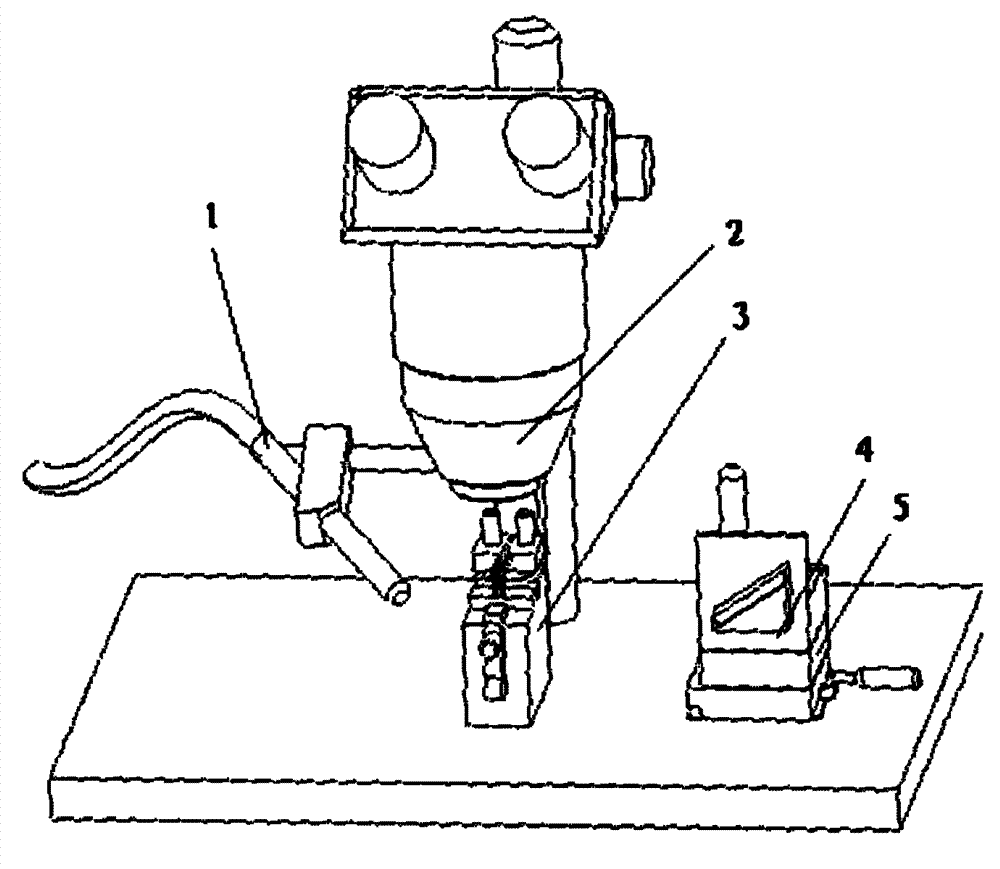
[0029] Figure 6 It is a schematic diagram of the overall structure of the optical fiber array plate assembly device in the present invention. The optical fiber array plate assembling device is composed of two parts, an L-shaped positioning base A and a clamp assembly B, and the two parts can be separated from each other.

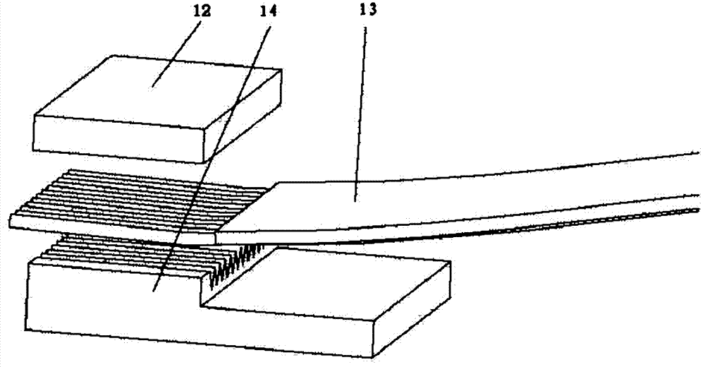
[0030] Figure 4A It is a structural schematic diagram of the above-mentioned L-shaped positioning base; the L-shaped positioning base A includes a side wall A1 and a base A2, the inside of the side wall is fixedly connected with a positioning block 6, and the inside of the side wall is also movably connected with a positioning block. 6 parallel pressing blocks 18, which can move horizontally along the inner side of the side wall to fix the array plate and press the optical fiber into the V-shaped groove of the array plate. A through hole 16a is ...


PUM


Abstract

The invention relates to a fiber array board assembly device and a fiber array board assembly platform using the same. The fiber array board assembly device comprises an L-shaped positioning base and a clamp component. The L-shaped positioning base comprises a side wall and a base. A positioning block is fixedly connected to the inner side of the side wall. A pressure block parallel to the positioning block is also movably connected to the inner side of the side wall. The pressure block can horizontally move along the inner side of the side wall. The inner side of the side wall is further provided with a clamp groove. The base is provided with a through hole. A lifting member and a support member are disposed in the through hole. A U-shaped support is disposed on two side walls of the clamp component. An elastic member is arranged between the bottom of the U-shaped support and the bottom of the clamp component. A glass pressure block is arranged between two ends of the U-shaped support. One end of the clamp component is provided with a protrusion which is clamped in the clamp groove. The lifting member controls the U-shaped support to ascend and descend through the support member.

Description

technical field [0001] The invention relates to an assembly device, in particular to an assembly device for an optical fiber array board and an assembly platform for an optical fiber array board using the device. Background technique [0002] With the development of optical fiber communication industry, optical fiber transmission lines in this field have a good application prospect. However, the packaging technology for optical fibers has always been a technical difficulty in this field. The essence of FA (Fiber Array, fiber array) packaging is to place the fiber array into the V-groove substrate with a specific packaging fixture, so that the fibers in the fiber array enter the grooves in the V-groove substrate one by one, and then use a specific glue , such as UV glue to stick it together. One of the difficulties is the precise positioning of the V-groove and the fiber array before dispensing, which requires the assembly device of the fiber array board to make the V-groov...

Claims


Application Information

Patent Timeline
Patent Type & Authority Applications(China)
IPC IPC(8): B25B11/02F16B11/00
Inventor 何祺昌
Owner 广东安捷康光通科技有限公司
Why Eureka
Try Eureka