A fuel filler molding method and preparation device used in two-piece blow molding process

A molding method and blow molding technology, applied in the field of fuel tank blow molding manufacturing, can solve the problems of increased evaporative emissions of hydrocarbons, difficulties in meeting emission regulations, and high costs, and achieve low cost, reduced cost, and easy operation Effect

Active Publication Date: 2016-06-08
YAPP AUTOMOTIVE PARTS
View PDF5 Cites 0 Cited by
  • Summary
  • Abstract
  • Description
  • Claims
  • Application Information

AI Technical Summary

Problems solved by technology

Since the traditional fuel filler is connected to the tank body through punching and welding after the fuel tank is blow-molded, on the one hand, punching and welding will easily lead to a higher increase in the evaporative emission value of hydrocarbons, which is difficult to meet the most stringent requirements in California, the United States. The state's PZEV and LEVIII vehicle emission regulations require 54mg / day; on the other hand, due to the high cost of fuel filler injection molding parts, it is also necessary to reduce the cost of fuel filler to reduce the unit cost of the fuel tank assembly

Method used


Image

  • A fuel filler molding method and preparation device used in two-piece blow molding process
  • A fuel filler molding method and preparation device used in two-piece blow molding process
  • A fuel filler molding method and preparation device used in two-piece blow molding process

Examples


Embodiment 1

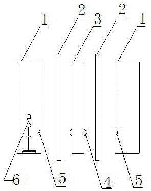
[0035] see figure 1 — Figure 6 , in order to achieve the above object, the technical scheme of the present invention is as follows, a fuel filler filler molding method applied in the two-piece blow molding process, the molding method includes the following steps, see figure 1 ,

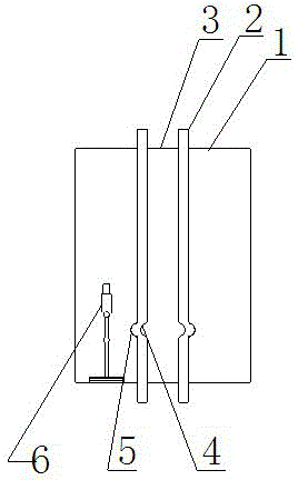
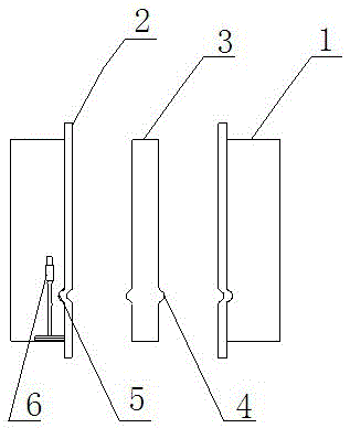
[0036] 1) Feeding, this step is mainly two pieces, the molten parison is respectively fed into the two gaps formed by the preform template 3 and the two mold halves 1; see figure 2 , 2) The mold half 1 is closed with the preform template 3; 3) High pressure blow molding; see image 3 , 4) Mold 1 opens and preform template 3 exits; see Figure 4 , 5) The fuel filler extrusion molding device moves in; see Figure 5, 6) The mold half-mold 1 is closed again; 7) High-pressure blow molding, and the fuel filler is extruded; 8) The fuel filler extrusion molding device is moved out;

[0037] 9) The mold is fully opened again; 10) The product is taken out.

[0038] The main feature of this method is tha...

Embodiment 2

[0039] Embodiment 2: As a further improvement of the present invention, a cooling device is provided on the fuel filler extrusion molding device in the step 5. The cooling device adopts cooling water, and the cooling device enables sufficient cooling of the fuel filler structure and has sufficient strength to prevent deformation in the later stage. All the other results and advantages are exactly the same as in Example 1.

Embodiment 3

[0040] Embodiment 3: see figure 1 , as a further improvement of the present invention, in the step 2, the preform template 3 is provided with a protrusion 4, and the number of the protrusion 4 is two, which are symmetrically arranged on both sides of the preform template 3, and the mold The mold half 1 is provided with a groove 5 corresponding to the protrusion 4 . There is a protruding structure at the filling port of the fuel tank corresponding to the preform template 3 device, and a groove structure is provided on the mold. After closing with the mold, the external shape of the filling port is formed when the structure is closed by the protrusion and the groove. The molding method is different from blow molding. It uses the blank of the fuel tank to form the external shape of the fuel filler while performing the preformed seal. After this process, the external structure of the fuel filler is formed in half on the left and right sides of the fuel filler. . All the other re...


PUM


Abstract

The present invention relates to a fuel filler forming method applied in a two-piece blow molding process, characterized in that the forming method comprises the following steps, 1) Feeding, this step is mainly to feed two pieces of plasticized parison into the two gaps formed by the preformed template and the mold half; 2) The mold half is closed with the preformed template; 3) High pressure blow molding ;4) The mold is opened, and the preformed template is withdrawn; 5) The fuel filler extrusion molding device is moved in; 6) The mold is closed again; 7) High pressure blow molding, and the fuel filler extrusion molding device is extruded; 8) Refueling The mouth extrusion molding device is removed; 9) The mold is fully opened again; 10) The product is taken out. The method involved in the present invention has simple steps, is easy to operate, effectively reduces production and unit cost, improves product performance and yield, reduces the investment in the later drilling and welding process, reduces the HC compound discharge value of the fuel tank, and can meet requirements of higher emissions regulations.

Description

technical field [0001] The invention relates to a fuel filler structure molding method and a preparation device used in a two-piece blow molding process. The fuel filler structure and its process method are suitable for the structure and connection between a two-piece hollow blow molding box and a fuel filler pipe. The method is especially suitable for the field of fuel tank blow molding manufacture. Background technique [0002] The HDPE6-layer co-extrusion blow molding technology with EVOH fuel barrier layer is the mainstream technology in the manufacture of plastic fuel tanks today. With the increasing awareness of environmental protection of the global government, relevant policies and regulations have imposed strict requirements on automobile OEMs, such as California has introduced PZEV, that is, quasi-zero emission regulations. For plastic fuel tanks produced by mainstream technologies, the total evaporative emissions, including the evaporative emissions of gasoline o...

Claims


Application Information

Patent Timeline
Patent Type & Authority Patents(China)
IPC IPC(8): B29C69/02B29C49/22B29C49/18B29C49/48B29C43/02B29C43/52
Inventor 孙岩姜林刘亮苏卫东王晔
Owner YAPP AUTOMOTIVE PARTS
Why Eureka
Try Eureka