Eureka AIR delivers breakthrough ideas for toughest innovation challenges, trusted by R&D personnel around the world.

Steering wheel device for steer-by-wire vehicles

A wire-controlled steering and steering wheel technology, which is applied to fluid steering mechanisms and other directions, can solve the problems of increasing the complexity of the assembly process, cab noise, high labor intensity for operators, and uncomfortable operation, and achieves the effect of good promotion and application value.

Inactive Publication Date: 2013-10-23
QINGDAO UNIV OF SCI & TECH
View PDF5 Cites 6 Cited by
  • Summary
  • Abstract
  • Description
  • Claims
  • Application Information

AI Technical Summary

Problems solved by technology

Especially on construction machinery, especially loaders, the steering system has higher requirements. The existing main technical solution is to install a full hydraulic steering gear at the bottom of the steering wheel, and control the flow to the steering cylinder by turning the steering wheel. This steering method There are many problems. First, since the selected steering gear is fixed, the number of turns of the steering wheel required to go from one limit position to another limit position during steering is also fixed. When carrying out loading operations, frequent large-angle steering is required In order to complete the work, the labor intensity of the operator is very high
Secondly, the driver does not have a suitable road feeling during driving, and the operation is uncomfortable. Thirdly, since the full hydraulic steering gear needs to be installed at the lower end of the steering wheel, the pipeline must be led near the cab, which increases the assembly process. complexity and noise in the cab

Method used


Image

  • Steering wheel device for steer-by-wire vehicles
  • Steering wheel device for steer-by-wire vehicles
  • Steering wheel device for steer-by-wire vehicles

Examples


Embodiment Construction

[0014] The present invention will be described in further detail below in conjunction with the accompanying drawings and specific embodiments.

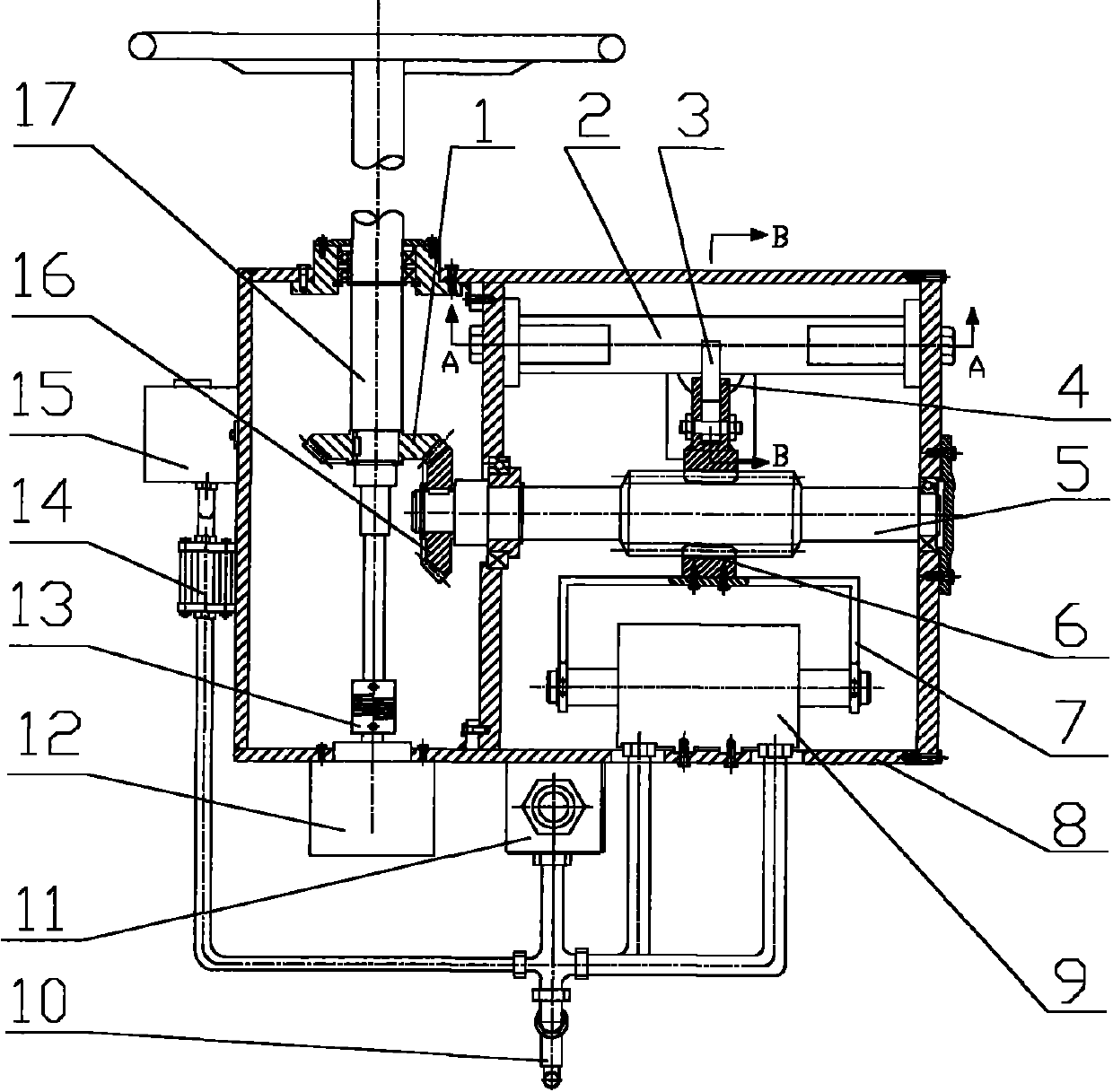
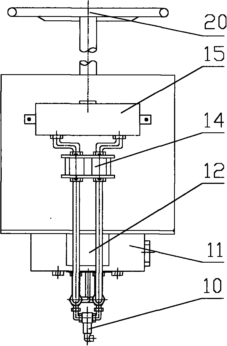
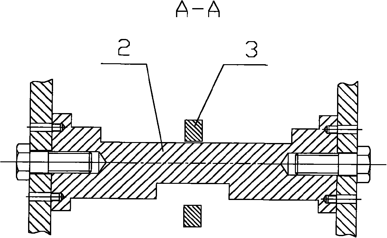
[0015] exist figure 1 , figure 2 , image 3 and Figure 4 Among them, the device is mainly composed of driving bevel gear 1, stroke baffle 2, limit block 3, block support seat 4, screw shaft 5, transmission nut 6, linkage rod 7, box body 8, oil cylinder 9, pressure difference Sensor 10, proportional throttle valve 11, angular displacement sensor 12, shaft coupling 13, fuel supply valve 14, fuel tank 15, driven bevel gear 16, drive shaft 17, electromagnet 18, return spring 19 and steering wheel 20; The angular displacement sensor 12 is fixedly installed on the casing 8 by bolts, the rotating rod of the steering wheel 20 is fixedly connected with the upper end of the driving shaft 17 through a shaft coupling, and the lower end of the driving shaft 17 is connected with the angular displacement through a shaft coupling 13. The input ...


PUM


Abstract

The invention discloses a steering wheel device for steer-by-wire vehicles, and aims to accurately detecting the rotary angle of a steering wheel, providing a proper and adjustable road feeling for a driver, changing the work modes under different work conditions and adjusting the full-steering rotary turn numbers of the steering wheel. A driving shaft is fixedly connected with an input shaft of an angular displacement sensor by a coupler, a transmission nut and a screw shaft are mounted in a match and transmission mode, a return spring is fixedly connected with the transmission nut by a support, an electromagnet is fixedly connected with the transmission nut, an iron core of the electromagnet and a baffle are connected by a pin shaft, grooves with different lengths are arranged on the frond and rear sides of a stroke baffle, the transmission nut is fixedly connected with a linkage rod, a work oil port of an oil cylinder is correspondingly connected with a work oil port of a proportional throttle valve by a pipeline, and a differential pressure sensor is arranged between two work oil pipelines of the oil cylinder. The steering wheel device for the steel-by-wire vehicles is suitable for engineering vehicles to be used as the steer-by-wire steering wheels.

Description

technical field [0001] The invention relates to a vehicle steering device, in particular to a steering wheel device for a steering-by-wire vehicle. Background technique [0002] The function of the steering system is to control the driving direction of the vehicle. The system should be able to keep the vehicle running in a straight line stably and flexibly change the driving direction according to the requirements. The basic requirements for the steering system are light and flexible operation, stable and reliable operation, and economical and durable use. The steering performance is an important factor to ensure the safe driving of the vehicle, reduce the labor intensity of the driver, and improve the work productivity. The steering system is a key assembly that determines vehicle safety and operating efficiency. [0003] With the improvement of application conditions and the development of modern technology, the performance of vehicle steering system needs to be further i...

Claims


Application Information

Patent Timeline
Patent Type & Authority Applications(China)
IPC IPC(8): B62D5/22
Inventor 王安敏黄凯吕枝恩王洛阳
Owner QINGDAO UNIV OF SCI & TECH
Why Eureka
Eureka Blog
Learn More