
Evaporation device

A technology of vapor deposition and vapor deposition of materials, which is applied in the directions of vacuum evaporation plating, sputtering plating, ion implantation plating, etc., can solve problems such as thermal deterioration, increased residual materials, and inability to obtain materials, so as to prevent thermal deterioration Effect

Active Publication Date: 2013-10-23
HITACHI ZOSEN CORP
View PDF3 Cites 9 Cited by
  • Summary
  • Abstract
  • Description
  • Claims
  • Application Information

AI Technical Summary

Problems solved by technology

However, when heating at high temperature for a long time, in the case of using a vapor deposition material with poor thermal stability, thermal deterioration occurs and the characteristics of the material cannot be obtained.
Conversely, when the temperature of the crucible is set to a low temperature, the evaporation amount of the vapor deposition material decreases, and even if a flow rate adjustment valve is used, it is difficult to maintain a predetermined vapor deposition rate stably for a long time, and residual material in the crucible also occurs. The problem of wasting vapor deposition materials due to excessive

Method used


Image

  • Evaporation device
  • Evaporation device
  • Evaporation device

Examples


Embodiment Construction

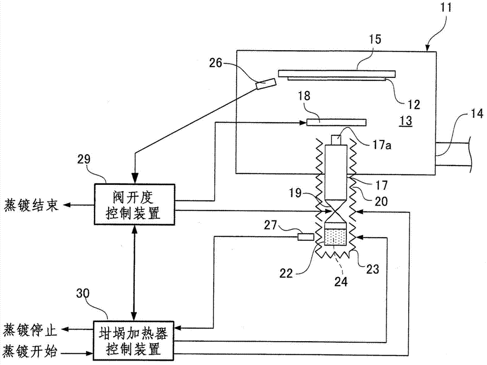
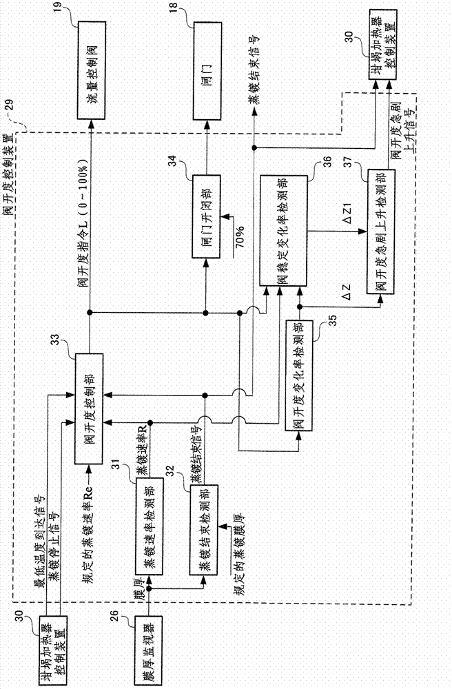
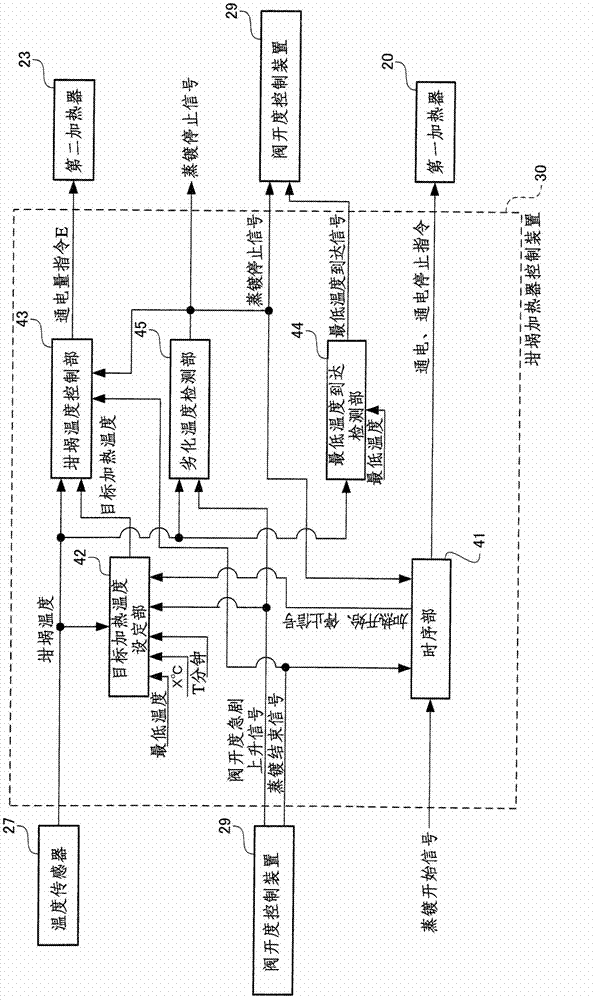
[0019] figure 1 is a structural diagram of an embodiment of the vapor deposition apparatus of the present invention. Such as figure 1 As shown, a vapor deposition chamber 13 is provided in a vacuum chamber (vacuum tank / vapor deposition container) 11, and in the vapor deposition chamber 13, a glass substrate (an example of a vapor deposition member) 12 is deposited in a vacuum atmosphere. Evaporation particles (evaporated evaporation materials such as organic EL materials) are deposited on the surface (lower surface). The vacuum chamber 11 is formed with a vacuum port 14 through which the vacuum chamber is formed into a vacuum atmosphere by a vacuum unit (not shown). The upper part of the vacuum chamber 11 is provided with a workpiece holder 15 that holds the glass substrate 12 . The illustrated vapor deposition device is an upward vapor deposition type (upward deposition) vapor deposition device, and vaporized particles are deposited from below toward the lower surface (dep...


PUM


Abstract

The invention provides an evaporation device. Evaporation is performed under minimum limit temperature of a crucible necessary for a specified evaporation rate, when evaporation material (24) in the crucible (22) reduces and the evaporation amount (formation of evaporation particles supplied from the crucible (22)) of the evaporation material (24) from the crucible reduces and thereby leading to reduction of the evaporation rate, and to maintain the specified evaporation rate and in the circumstance that the aperture of a flow control valve (19) is largened sharply, a target heating temperature of the crucible rises with an incremental quantity. The result is that the evaporation amount of the evaporation material (24) form the crucible (22) increases, and the specified evaporation rate is maintained. By enabling the target temperature to rise with an incremental quantity successively, not only thermal degradation of the evaporation material (24) can be prevented and the evaporation material (24) can be used to the end, but can also reduce residues of the evaporation material (24) to a minimum value.

Description

technical field [0001] The present invention relates to an evaporation device for evaporating metal thin films, organic material thin films, metal electrode wiring of solar cells and display panels, organic EL light-emitting layers, and the like. Background technique [0002] Generally, the vapor deposition used to form the above-mentioned thin film etc. is performed within 10 -4 It is carried out under high vacuum above Pa. For example, in the vacuum evaporation device shown in Japanese Patent Laid-Open Publication No. 2004-91858, a crucible and a substrate to be evaporated are provided in a vacuum chamber (vacuum container). Plating material. After evacuating the vacuum chamber and reaching the above-mentioned high vacuum, the crucible is heated by an electric heater to melt and evaporate the vapor deposition material in the crucible, and make the melted vapor deposition material adhere to the substrate to be vapor deposited, thereby forming a thin film. The vapor depos...

Claims


Application Information

Patent Timeline
IPC IPC(8): C23C14/24
CPCC23C14/243C23C14/26C23C14/545
Inventor 大工博之菊地昌弘松本祐司
Owner HITACHI ZOSEN CORP
Learn More