

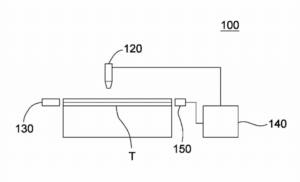
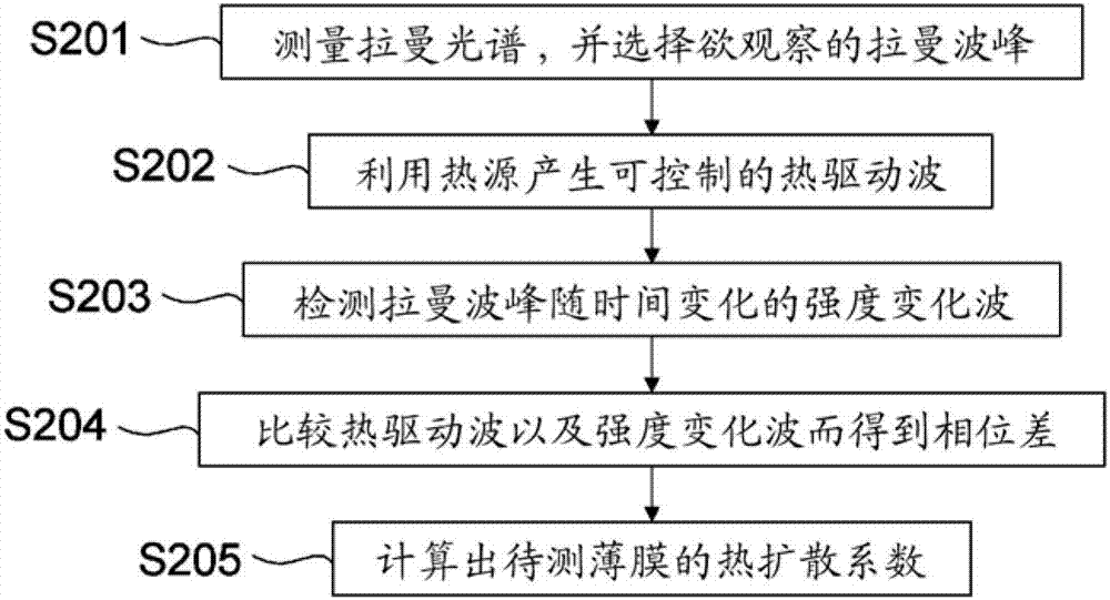
Apparatus and method for measuring thermal diffusivity
A thermal diffusivity and heat-driven technology, applied in Raman scattering, material excitation analysis, etc., can solve the problems that the spatial resolution cannot be less than 250nm, and the multilayer film cannot be measured, and achieve the effect of less requirements
- Summary
- Abstract
- Description
- Claims
- Application Information
AI Technical Summary
Problems solved by technology
Method used
Image

Examples
experiment example 1
[0070] Piece to be tested (film / substrate to be tested): diamond-like carbon film (DLC, 180nm) / Si(100) substrate
[0071] Raman spectrometer: High-resolution confocal Raman Microscope (Lab RAM HR Raman Microscope, HOROBA), HeNe laser: wavelength 632.8nm, power: 20mW; magnification: objective lens 100X, aperture 0.9; resolution: focal length division 1μm.
[0072] Heating equipment: near-infrared light heating unit, the temperature control range is 50℃~82℃.
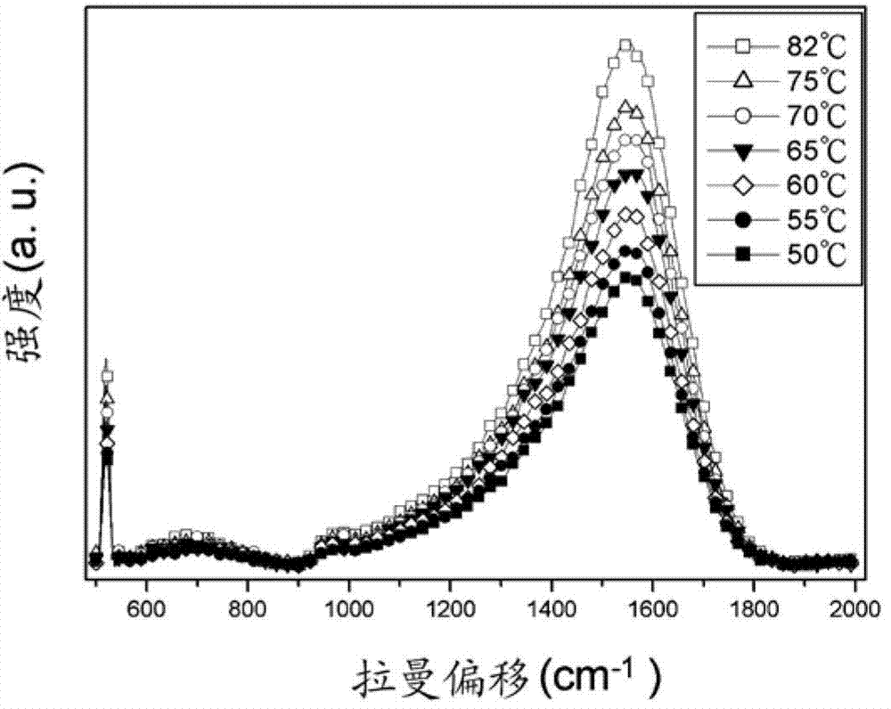
[0073] The piece to be tested is placed on the platform, and the Raman spectrum of the piece to be tested is measured by a Raman spectrometer. At this time, a wave peak at Raman shift (Raman shift) is 519.12cm -1 The location of and another peak in the Raman shift is about 1550cm -1 s position. At Raman shift (Raman shift) is 519.12cm -1 The peak at the position represents the signal of Si, and the Raman shift (Raman shift) is 1550cm -1 The position of the peak represents the DLC signal.
[0074] Next, a near-infrare...
PUM
 Abstract
Description
Claims
Application Information