
Small-beam-spot X-ray equipment

An X-ray and beam spot technology, applied in the direction of X-ray tube electrodes, X-ray tube components, etc., can solve problems such as poor imaging quality, large X-ray beam spot area, damage, etc., to avoid unnecessary damage, high definition effect

Inactive Publication Date: 2013-10-23
HANGZHOU DIANZI UNIV
View PDF4 Cites 2 Cited by
  • Summary
  • Abstract
  • Description
  • Claims
  • Application Information

AI Technical Summary

Problems solved by technology

[0003] The cathode emission point source area of ​​the traditional filament electron gun is large, so the size of the electron source is also relatively large (about 50-100 μm), which makes the X-ray beam spot area generated by the cathode X-ray tube larger and the imaging quality is poor. Moreover, due to X-ray photons are scattered. When the X-rays with a large beam spot act on the subject, parts of the body that do not need to be inspected will also receive part of the X-ray irradiation, thereby causing damage to the subject.

Method used


Image

  • Small-beam-spot X-ray equipment

Examples


Embodiment Construction

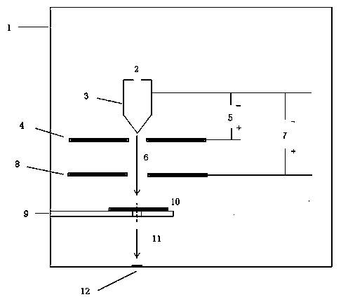
[0009] Such as figure 1 As shown, the field emission electron gun cathode device is housed in the vacuum X-ray sealing sleeve 1 . The field emission electron gun cathode device includes a field emission filament 3 connected to a flash power supply 2 . A field emission power supply 5 is connected between the field emission filament 3 and the anode 4 of the field emission power supply. The field emission filament 3 emits an electron beam 6 under the strong electric field generated by the field emission power supply 5 . The electron beam 6 moves to the anode 8 of the acceleration power supply through the acceleration power supply 7, and obtains high energy after acceleration. The high-energy electron beam irradiates on the target 10 cooled by the ring-shaped target cooling water device 9 to generate X-rays 11. Since the target 10 is relatively Thin, the generated X-rays 11 exit the X-ray tube through the beryllium window 12.


PUM


Abstract

The invention discloses small-beam-spot X-ray equipment. A conventional filament electronic gun has the defects of large area of a cathode emitting point source and larger size of an electronic source size. A field emitting electronic gun cathode device is arranged in a X-ray sealing sleeve; the field emitting electronic gun cathode device comprises a field emitting filament connected with a flashing power supply; a field emitting power supply is connected between the field emitting filament and a field emitting power supply anode; the field emitting filament is used for emitting electronic beams under a strong electronic field generated by the field emitting power supply; the electronic beams move towards an accelerating power supply anode through an accelerating power supply, and obtain high energy and become high-energy electronic beams after being accelerated; the high-energy electronic beams are irradiated onto a target cooled by using an annular target cooling water device to generate X-rays; and the generated X-rays are emitted out of the X-ray sealing sleeve through a beryllium window. According to the small-beam-spot X-ray equipment, the electronic beams of very small beam spots generated by a field emitting cathode are used for exciting an anode target, and the light spot effects of the X-rays can reach an approximate spot light source effect.

Description

technical field [0001] The invention belongs to the technical field of medical devices, and relates to a small-beam spot X-ray device. Background technique [0002] In medicine and industry, X-ray equipment is used for diagnosis. Such an x-ray system has an x-ray radiator which in turn includes an x-ray tube for generating x-rays. In an evacuated X-ray tube, there is a cathode that emits electrons. These electrons are accelerated towards the anode by high voltage, and finally penetrate into the anode material, thereby generating X-rays. [0003] The cathode emission point source area of ​​the traditional filament electron gun is large, so the size of the electron source is also relatively large (about 50-100 μm), which makes the X-ray beam spot area generated by the cathode X-ray tube larger and the imaging quality is poor. Moreover, due to X-ray photons are scattered. When X-rays with a large beam spot act on the subject, parts of the body that do not need to be inspecte...

Claims


Application Information

Patent Timeline
IPC IPC(8): H01J35/06
Inventor 李红霞席俊华季振国李阳阳张峻
Owner HANGZHOU DIANZI UNIV
Learn More