
Ion beam bending magnet for a ribbon-shaped ion beam

A technology of bending magnets and ion beams, applied in discharge tubes, electrical components, circuits, etc., can solve problems such as increased difficulty of analyzer magnets

Active Publication Date: 2013-10-23
NISSIN ION EQUIP CO LTD
View PDF10 Cites 4 Cited by
  • Summary
  • Abstract
  • Description
  • Claims
  • Application Information

AI Technical Summary

Problems solved by technology

The difficulty of constructing suitable analyzer magnets increases with the large size of the ribbon beam to be analyzed

Method used


Image

  • Ion beam bending magnet for a ribbon-shaped ion beam
  • Ion beam bending magnet for a ribbon-shaped ion beam
  • Ion beam bending magnet for a ribbon-shaped ion beam

Examples


Embodiment Construction

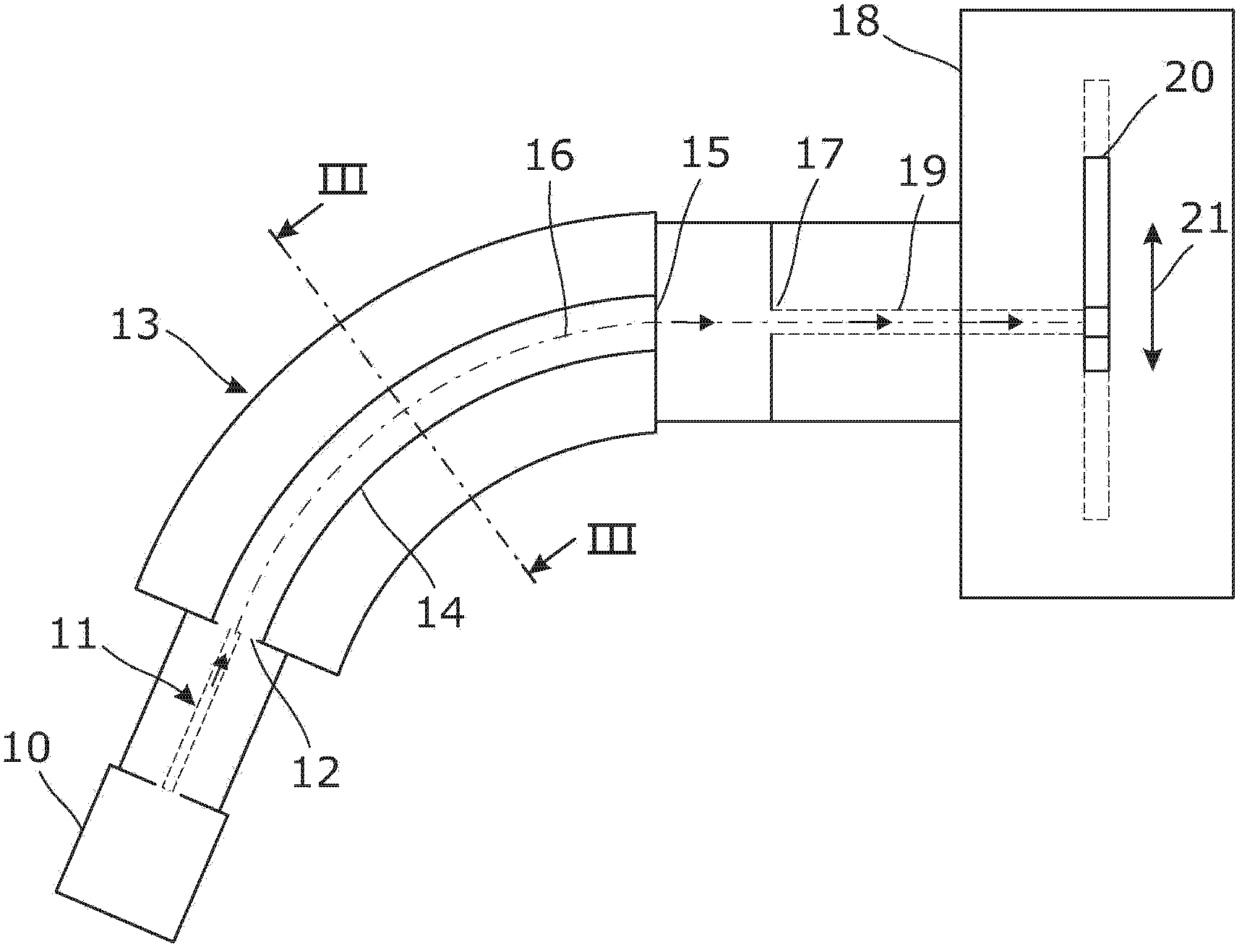
[0035] Ion bending magnets embodying the invention can be used in the field of ion implantation, in particular in the implantation of relatively large flat panels for the production of flat panel display devices. figure 1 is a schematic diagram illustrating some basic components of an ion implanter incorporating an ion beam bending magnet embodying the invention.

[0036] exist figure 1In , ions to be implanted are obtained from an ion source 10 to form an ion beam 11 , and the ion beam 11 enters an entrance 12 of an ion beam bending magnet 13 . Those skilled in the art of ion implantation will be familiar with the various types of ion sources that may be suitable as ion source 10 . In a typical ion source used in the field, a donor material comprising atoms or molecules implanted with the desired ion species is introduced into the chamber. Energy is delivered to the chamber, for example by a discharge, to form a plasma containing the desired species of ions in the chamber. ...


PUM


Abstract

An ion beam bending magnet provides a curved path through the magnet for bending a ribbon-shaped ion beam having its major cross-sectional dimension normal to the bending plane of the magnet. The magnet comprises a ferromagnetic yoke surrounding the beam path and having an internal profile in cross-section formed of four angled sides. These sides are angled to the major dimension of the ribbon beam passing through the magnet, so that the internal profile of the yoke is relatively wide in the center of the ribbon beam and relatively narrow near the top and bottom edges of the ribbon beam. Electrical conductors against the internal surfaces of the yoke provide a uniform distribution of electrical current per unit length along the angled sides of the profile, providing a substantially uniform magnetic bending field within the magnet yoke.

Description

technical field [0001] The present invention relates to ion beam bending magnets, and in particular to magnets adapted to accommodate and bend ribbon-shaped ion beams, the cross-sectional profile of which has a major dimension perpendicular to the bending plane of the magnet. Moreover, this invention relates to the ion beam irradiation apparatus, such as the ion implantation apparatus provided with the said ion beam bending magnet. Background technique [0002] Magnets for bending the path of an ion beam are known in a number of applications, in particular in the field of ion implantation. One application of curved magnets in ion implantation is for filtering an ion beam from an ion source to produce a filtered beam comprising substantially only ions with a desired mass / charge ratio. It is also well understood in the art that when a beam containing ions having a predetermined energy passes through a region of a substantially uniform magnetic field in a direction transverse ...

Claims


Application Information

Patent Timeline
Patent Type & Authority Applications(China)
IPC IPC(8): H01J37/05H01J37/317
CPCH01J37/1475H01J2237/055H01J2237/1523H01J2237/31701H01J37/05H01J37/147H01J37/14H01J37/08H01J37/317
Inventor 希尔顿·F·格拉维斯土肥正二郎本杰明·托马斯·金
Owner NISSIN ION EQUIP CO LTD
Learn More