Absorber

A technology of absorption tubes and reaction vessels, applied in the field of absorbers, can solve problems such as expensive materials, and achieve the effects of increasing absorption efficiency, increasing volume flow, and increasing contact area

Inactive Publication Date: 2013-10-23
WESTEC ENVIRONMENTAL SOLUTIONS
View PDF2 Cites 5 Cited by
  • Summary
  • Abstract
  • Description
  • Claims
  • Application Information

AI Technical Summary

Problems solved by technology

A further disadvantage of most prior art absorbers is that they require relatively expensive materials in their construction

Method used


Image

  • Absorber
  • Absorber
  • Absorber

Examples


Embodiment Construction

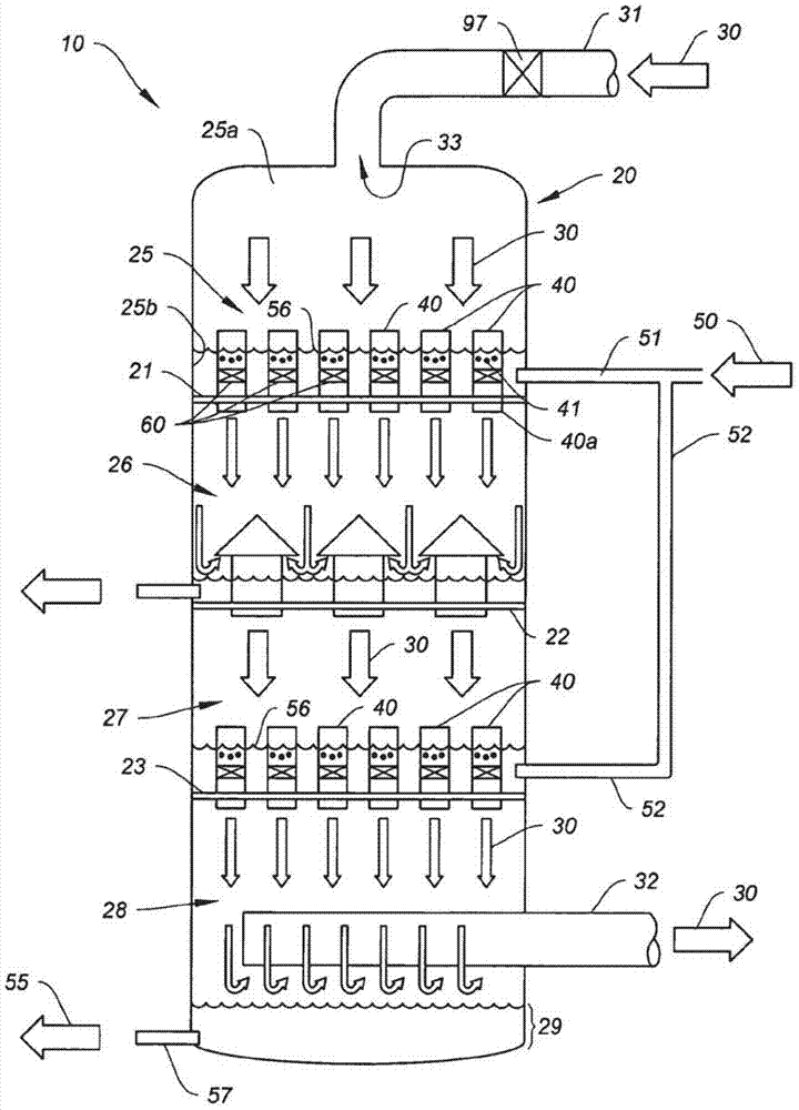
[0053] figure 1 A first embodiment of the invention is shown, referred to herein as a "Flood Tube Gas Absorber" (FTGA). It includes a reaction or absorber vessel 20, which as shown is a cylindrical, vertically extending vessel which in some applications may exceed 15 meters in diameter. The reaction or absorber vessel 20 may be of virtually any shape and have a circular, oval, rectangular, polyhedral, or other shaped cross-section.

[0054] An input flow stream 30 such as flue gas from a fossil fuel power plant flows into an inlet pipe 31 connected to an inlet 33 at the top or upper end of the vessel 20 . Gas stream 30 contains selected components to be absorbed, such as CO 2 , for example in the case of flue gas flow. The input flow gas stream 30 flows downwardly through the reaction or absorber vessel 20 and exits through the outlet pipe 32 after undergoing the absorption process described herein.

[0055] The reaction vessel 20 has a first chamber 25 and a second chambe...


PUM

PropertyMeasurementUnit
heightaaaaaaaaaa

Abstract

An absorber is provided which utilizes a solvent froth to absorb a selected component, such as CO2 for example, from a flowing gas stream, such as flue gas from a fossil fuel power plant, for example. In one embodiment, a flooded tube gas absorber utilizes a bulkhead plate extending across a reaction chamber. The plate carries a plurality of vertical absorption tubes, each carrying a plurality of spaced apart screens. The incoming gas stream flows downwardly and at equal velocities through the tubes. Solvent is injected downwardly into the tubes. The screen array forms a froth and rapidly and repeatedly bursts the froth bubbles, forming a rapidly changing absorption surface. A second embodiment uses full diameter screens without a bulkhead plate. An option is to use ridge shaped screens to achieve solvent pulsing, increasing efficiency. Both vertical and horizontal reaction chambers are disclosed.

Description

[0001] Cross References to Related Applications [0002] This application claims the benefit and priority of US Provisional Application Serial No. 61 / 463,194, filed February 14, 2011, and US Provisional Application Serial No. 61 / 626,493, filed September 27, 2011. Background technique [0003] A typical prior art absorber utilizes what is described herein as a static, fixed surface area on which absorption occurs. For example, a common absorber design is a "shaped packing" design. In this design, packing elements with complex surface shapes are placed in fixed-sized chambers. The liquid solvent is typically allowed to flow down and wet the fixed-dimensional outer surfaces of the unit. This provides a large surface area for mass transfer between solvent and gas. The gas is then driven up through the packing, and selected components of the gas are absorbed into the surface of the solvent. The surface area of ​​the packing remains fixed and static. The three commercial types ...

Claims


Application Information

Patent Timeline
Patent Type & Authority Applications(China)
IPC IPC(8): B01D47/00
CPCY02C10/06B01D53/1475B01D2258/0283B01D53/18Y02C20/40
Inventor C.杜根R.J.佩莱格林W.L.哈格罗夫Z.B.刘
Owner WESTEC ENVIRONMENTAL SOLUTIONS
Why Eureka
Try Eureka