Vehicle control device
A control device and vehicle technology, applied in vehicle energy storage, vehicle components, hybrid vehicles, etc., can solve the problems of only focusing on the clutch speed, not considering the inertia of the rotating elements, and not being able to fully avoid the engagement shock, etc., to achieve the purpose of suppressing torque Effect of change
Active Publication Date: 2013-10-30
NISSAN MOTOR CO LTD
View PDF7 Cites 11 Cited by
- Summary
- Abstract
- Description
- Claims
- Application Information
AI Technical Summary
Problems solved by technology
Method used
View moreImage
Smart ImageViewing Examples

Examples
Embodiment 1
[0025] First, the structure will be described.
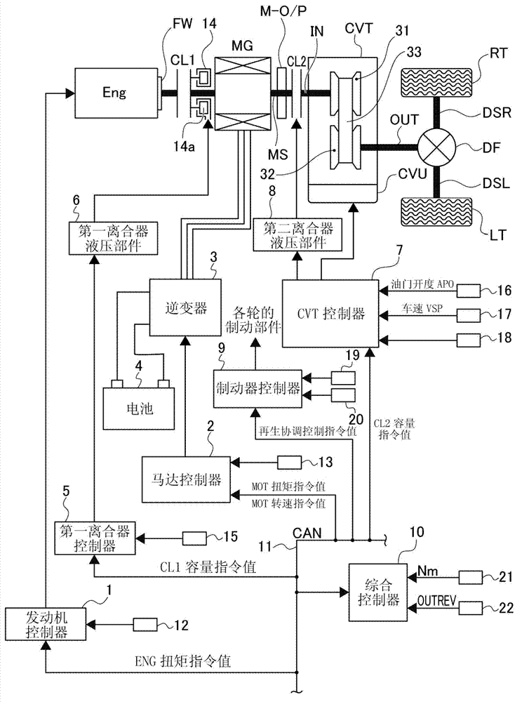
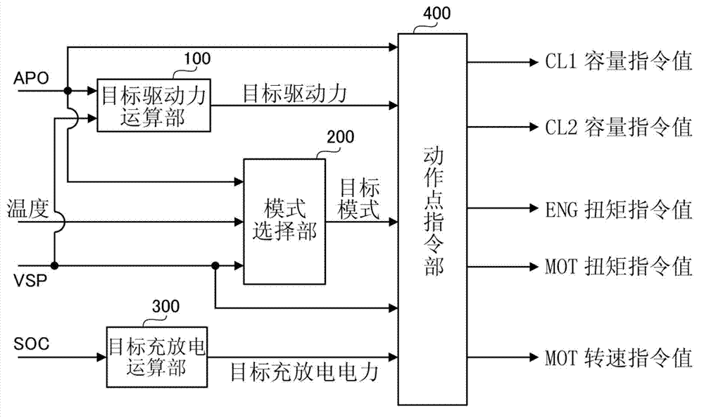
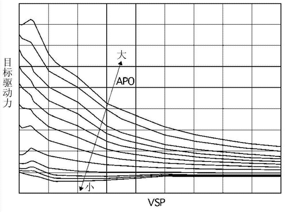
[0026] The structure of the control device of the hybrid vehicle (an example of the vehicle) of Embodiment 1 is divided into "system structure", "integrated calculation processing structure of integrated controller", "mode selection part structure", "operation command value calculation process structure" to explain.
Login to View More PUM
 Abstract
A vehicle control device suppresses change of torque output to driving wheels when a clutch is shifted from a full-joint state to a sliding joint state or from a sliding joint state to a full-joint state. The vehicle control device of a hybrid vehicle comprises a motor, an electric generator, a second clutch and an action instruction value calculating and processing structure, wherein the second clutch is arranged between the electric generator and left and right driving wheels, and the sliding joint WSC driving mode is shifted to a full joint HEV driving mode or vice versa. When the action instruction value calculating and processing structure is under an HEV driving mode, the ENG torque instruction value and MOT torque instruction value for the motor and the electric engine are set to a value obtained by adding a target transmission torque for the output shaft of the second clutch, namely T / M input target torque, to a torque of revolving rising inertial part (inertial torque) of the motor and the electric engine.
Description
technical field [0001] The present invention relates to a control device for a vehicle that provides a clutch between a drive source and a drive wheel and has a slip running mode of slip engagement and a clutch running mode of full engagement. Background technique [0002] Conventionally, as a control device for a hybrid vehicle, there is known a control device (see Patent Document 1) that determines whether the motor is driven based on a driver's request in a slipping travel mode in which the clutch between the motor and the driving wheels is slipped and engaged. Torque, on the other hand, set the transmission torque of the clutch to the transmission torque capacity of the input side rotation speed of the clutch (that is, the rotation speed of the motor) is approximately fixed. [0003] Patent Document 1: Japanese Patent Laid-Open No. 2001-263383 Contents of the invention [0004] The problem to be solved by the invention [0005] However, the above-mentioned conventio...
Claims
Login to View More Application Information
Patent Timeline
 Patent Type & Authority Applications(China)
IPC IPC(8): B60W20/00B60W10/06B60W10/08B60L50/16
CPCY02T10/6286Y02T10/7077Y02T10/6221Y02T10/60Y02T10/62Y02T10/7072
Inventor 安藤孝夫
Owner NISSAN MOTOR CO LTD
Features
- R&D
- Intellectual Property
- Life Sciences
- Materials
- Tech Scout
- Unparalleled Data Quality
- Higher Quality Content
- 60% Fewer Hallucinations
Learn More Browse by: Latest US Patents, China's latest patents, Technical Efficacy Thesaurus, Application Domain, Technology Topic, Popular Technical Reports.
© 2025 PatSnap. All rights reserved.Legal|Privacy policy|Modern Slavery Act Transparency Statement|Sitemap|About US| Contact US: help@patsnap.com