Vacuum pump blade with oil grooves and vacuum pump

A technology of vacuum pump and vane, applied in the field of vacuum pump and vane, can solve the problems of increased friction loss, poor sealing, easy wear, etc., and achieve the effect of small friction loss and long service life

Inactive Publication Date: 2015-11-25
OECHSLER PLASTIC PROD TAICANG
View PDF7 Cites 1 Cited by
  • Summary
  • Abstract
  • Description
  • Claims
  • Application Information

AI Technical Summary

Problems solved by technology

[0003] Since the blades are always in frictional contact with the side wall of the vacuum pump cavity and the inner side of the rotor slot, they are very easy to wear. With the wear of the blades, the friction loss continues to increase. At the same time, the gap between the blades, the side wall of the cavity and the rotor slot becomes larger. Resulting in reduced airtightness and further reduction in overall efficiency
Chinese patent CN20350006U discloses a vacuum pump with cylindrical rolling elements on the inside of the blades and rotor grooves to reduce the friction between the blades and the rotor during motion, but the contact mode between the cylindrical rolling elements and the inside of the rotor is point contact , there will be a lot of vibration and noise during the movement, and its sealing is not good, which will affect the working effect of the vacuum pump

Method used


Image

  • Vacuum pump blade with oil grooves and vacuum pump
  • Vacuum pump blade with oil grooves and vacuum pump
  • Vacuum pump blade with oil grooves and vacuum pump

Examples


Embodiment 1

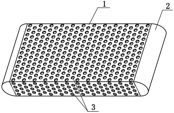
[0018] Such as figure 1 The shown vacuum pump blade with oil grooves includes a blade body 1 and an end portion 2. Several neatly arranged circular grooves 3 are arranged on the upper, lower, front and rear sides of the blade body 1. In the grooves 3 Inject an appropriate amount of lubricating oil. The blade is installed in the rotor 4, the blade body 1 passes through the groove of the rotor 4, and the gap between the blade body 1 and the inside of the groove of the rotor 4 is sealed by oil. The blade end 2 is tightly fitted with the inner lining ring of the vacuum pump 5, and the gap between the blade and the side wall of the inner chamber of the vacuum pump 5 is sealed by oil. When working, the rotor 4 drives the blades to rotate in the vacuum pump 5, and the end 2 further clings to the inner wall of the vacuum pump, and the blade body 1 reciprocates stably along the length direction of the blade body 1 in the rotor to further make the end 2 press the inner lining of the va...

Embodiment 2

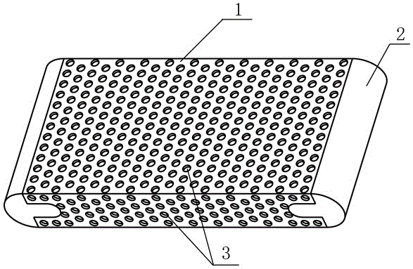
[0020] Such as figure 2 In the shown vacuum pump vane with oil grooves, the body 1 and the end 2 are detachable and connected to each other through shape fitting. Such as Figure 4 As shown, the blades are installed in the rotor 4, and the rest are the same as in the first embodiment.

Embodiment 3

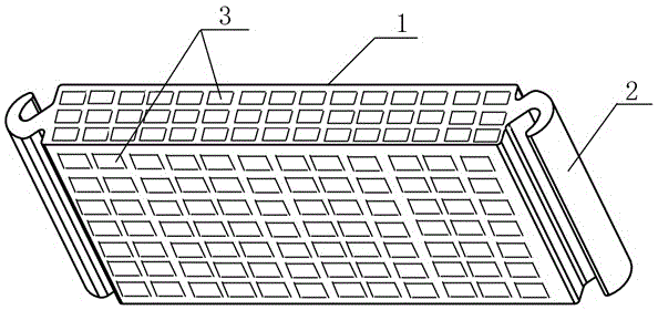
[0022] Such as figure 1 The vacuum pump blade with oil groove shown is different in that the vacuum pump blade includes a shell 11 and an insert 12, the shell 11 is made of polyphenylene sulfide-glass fiber, and the insert 12 is injection molded from a glass fiber composite board Formed or molded, the parts are joined together using injection molding. Such as Figure 4 As shown, several neatly arranged circular grooves 3 are arranged on the upper, lower, front, and rear surfaces of the shell 11 of the blade, and an appropriate amount of lubricating oil is injected into the grooves 3 . The blade is installed in the rotor 4, the blade body 1 passes through the groove of the rotor 4, and the gap between the blade body 1 and the inside of the groove of the rotor 4 is sealed by oil. The blade end 2 is tightly fitted with the inner lining ring of the vacuum pump 5, and the gap between the blade and the side wall of the inner chamber of the vacuum pump 5 is sealed by oil. When wor...


PUM


Abstract

The invention discloses a vacuum pump blade with oil grooves. The vacuum pump blade comprises a blade body and ends and is characterized in that the surface of the blade body is provided with a plurality of grooves. The surface of the blade body of the vacuum pump is provided with the grooves for storing oil, and friction between the blade and the side wall of an inner cavity of the vacuum pump and between the blade and the inner side of a groove of a rotor can be lowered in the rotating process of the blade, so that heat generation is lowered, noise is lowered, power consumption is reduced, and the service life is prolonged.

Description

technical field [0001] The present invention relates to a vane for use in a vacuum pump, particularly but not exclusively for use in automotive applications. The invention relates to a vacuum pump having such a blade. Background technique [0002] The vacuum pump is used in the service brake system, and the rotary vane vacuum pump is used to provide vacuum negative pressure for the vacuum booster. As the rotor rotates, the vanes rotate with the rotor and pass through the rotor to engage the housing wall at each end thereof, the gap between the vanes and the wall being sealed by an oil film. As the blades rotate, a vacuum is created that draws gas into the cavity through the inlet, which is then expelled through the outlet as the blades rotate. [0003] Since the blades are always in frictional contact with the side wall of the vacuum pump cavity and the inner side of the rotor slot, they are very easy to wear. With the wear of the blades, the friction loss continues to inc...

Claims


Application Information

Patent Timeline
Patent Type & Authority Applications(China)
IPC IPC(8): F04C29/00F04C29/02F04C29/06F04C25/02F04C18/344
Inventor 胡焕波黄建昌张为刘蔡松波
Owner OECHSLER PLASTIC PROD TAICANG
Why Eureka
Try Eureka