
Eureka
For R&D, Eureka makes reading and utilizing patents & technical documents easy.
Eureka AIR
Designed for self-driven R&D workflows. Generate viable solutions, solve complex R&D challenges, empower your innovation with AI.

Eureka Materials
Designed for material experts only. Revolutionize your material R&D, from search, analyze, to developing new materials.

TechResearch
Generate reliable direction feasibility study reports for your R&D in just a few steps.

TechSeek
Discover and master advanced knowledge NOW. Basics, ideas, possibilities, all at once.

TechMind
As an expert in R&D Theories, TechMind can generates customized viable solutions instantly.

TechRisk
Analyze your overall solution with one click, know your potential R&D risks in advance.

TechMonitor
Get weekly tech updates, stay abreast of the latest tech innovations and key insights.
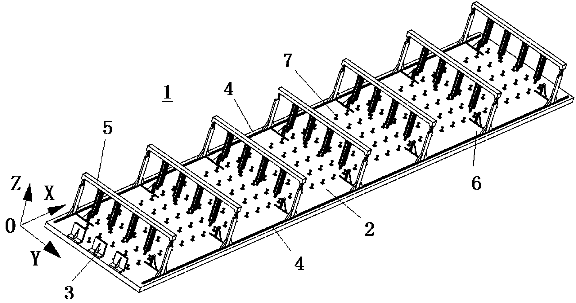
Flexible tool for detecting and machining aircraft wing panel profile and detecting and machining method
A flexible tooling and surface detection technology, which is applied in aircraft assembly, measuring devices, aircraft parts, etc., can solve the problems of easy manufacturing errors, large external dimensions, and the inability to meet the requirements of the overall composite wall panel of the wing, achieving high accuracy Degree and automation, improve production efficiency and quality, shorten the effect of quality inspection cycle
- Summary
- Abstract
- Description
- Claims
- Application Information
AI Technical Summary
Problems solved by technology
Method used
Image

Examples
Embodiment Construction
[0045] The present invention will be described in detail below in conjunction with specific embodiments. The following examples will help those skilled in the art to further understand the present invention, but do not limit the present invention in any form. It should be noted that those skilled in the art can make several modifications and improvements without departing from the concept of the present invention. These all belong to the protection scope of the present invention.
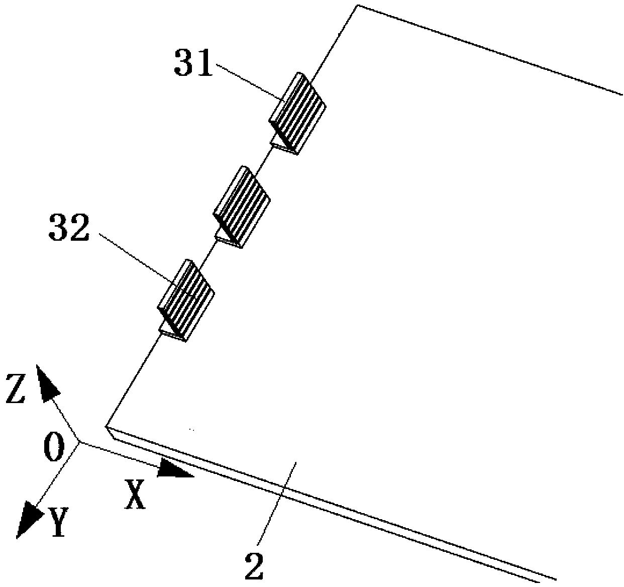
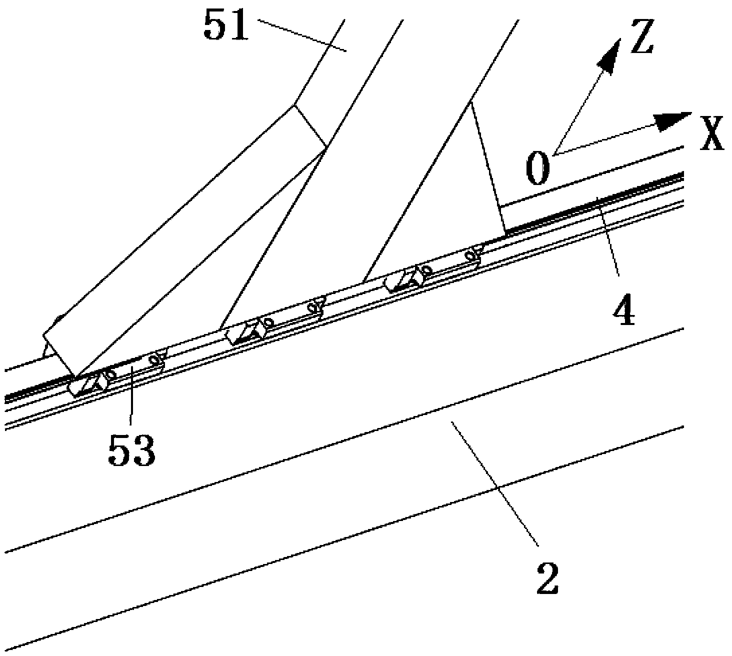
[0046] In order to make the present invention easy to understand, some directional terms are used in this specification. It should be noted that the directional terms mentioned in this specification, such as "up", "down", "left", "right", "front", "rear", etc., refer to the directions of the drawings. The positive direction of X is right, the negative direction of X is left, the positive direction of Y is front, the negative direction of Y is back, the positive direction of Z is up, and the negati...
PUM
 Abstract
Description
Claims
Application Information
 - R&D Engineer
- R&D Manager
- IP Professional
- Industry Leading Data Capabilities
- Powerful AI technology
- Patent DNA Extraction
Browse by: Latest US Patents, China's latest patents, Technical Efficacy Thesaurus, Application Domain, Technology Topic, Popular Technical Reports.
© 2024 PatSnap. All rights reserved.Legal|Privacy policy|Modern Slavery Act Transparency Statement|Sitemap|About US| Contact US: help@patsnap.com