
Nozzle for pulverized coal

A pulverized coal and nozzle technology is applied to a pulverized coal nozzle for blast furnace pulverized coal injection. effect of quantity

Inactive Publication Date: 2013-10-30
无锡市释珑能源科技有限公司
View PDF8 Cites 1 Cited by
  • Summary
  • Abstract
  • Description
  • Claims
  • Application Information

AI Technical Summary

Problems solved by technology

The main problem is: its internal structure is only a section of hollow cone, in several small holes or "Y" or "ten" shaped narrow slits connected with the hollow cone, the test shows that due to the flow of pulverized coal in the spray gun Layer problem, the hollow cone will cause uneven distribution of coal powder between different small holes or narrow slits; at the same time, when the nozzle is made of metal materials, the hollow cone wall inside the nozzle wears quickly, making The above-mentioned uneven distribution phenomenon will be aggravated with the prolongation of the use time of the nozzle; in severe cases, the pulverized coal stream will directly wear through the hollow cone wall, which will make the several small holes set in the patent application or "Y" or "ten" ” shaped slit, losing the ability to distribute coal powder

Method used


Image

  • Nozzle for pulverized coal
  • Nozzle for pulverized coal
  • Nozzle for pulverized coal

Examples


Embodiment Construction

[0023] Such as figure 1 , 2 , 3,4 are embodiment 1. Such as Figure 5 , 6 For example 2.

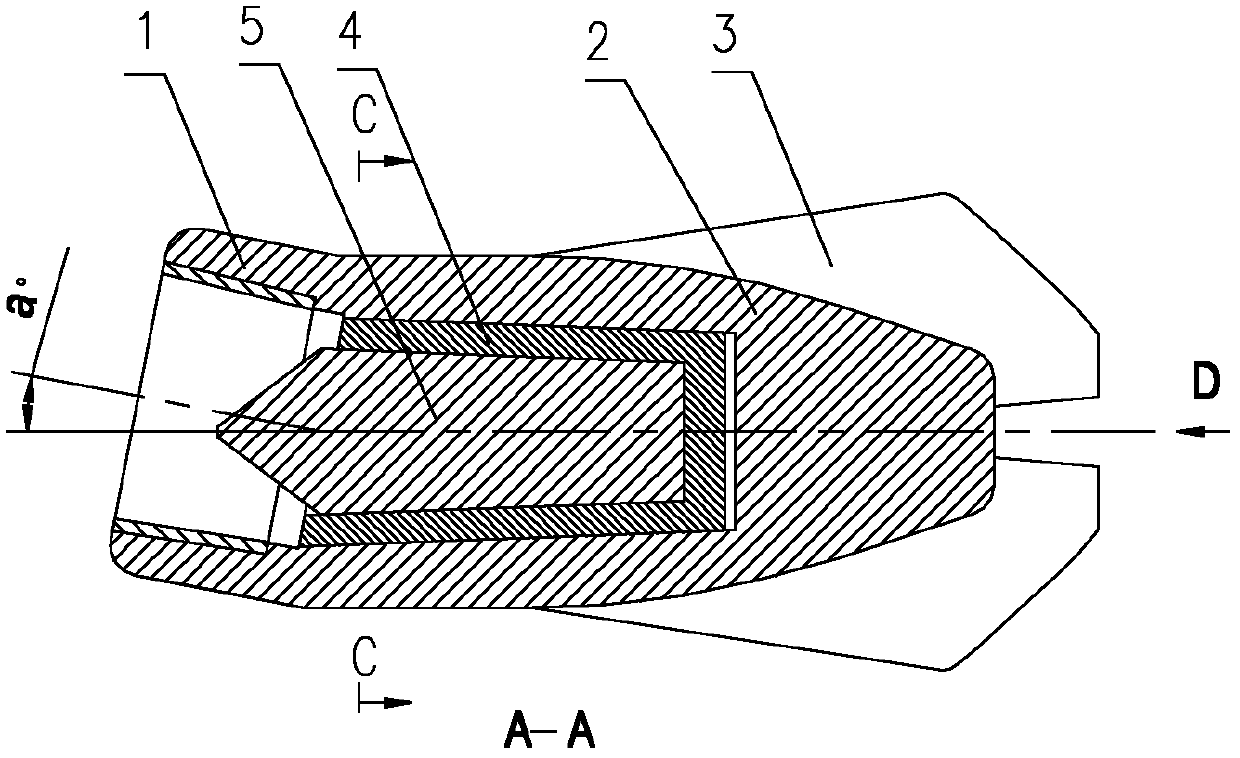
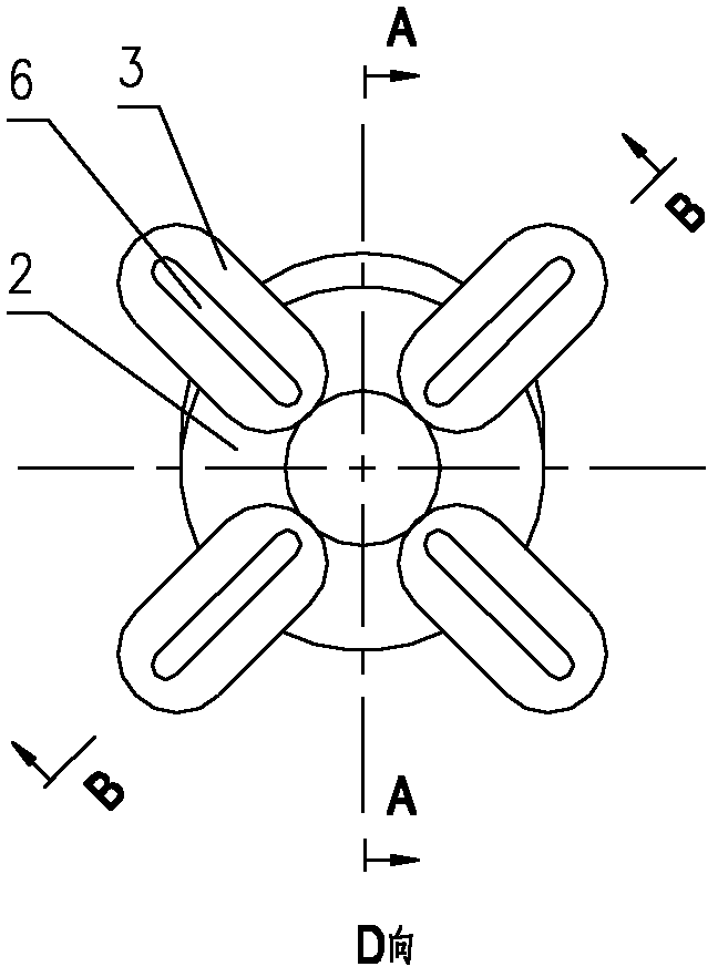
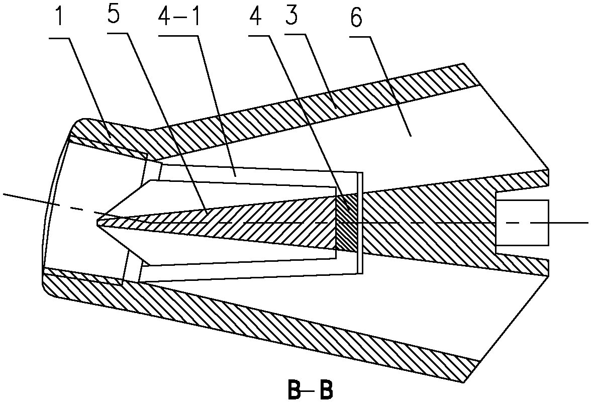
[0024] Such as figure 1 As shown, the pulverized coal nozzle is composed of an interface section 1, a cone section 2, a nozzle pipe 3, a wear-resistant sleeve 4, and a distribution cone 5. The included angle between the centerline of the interface section 1 and the cone section 2 is 0-15°. Such as figure 2 As shown, on the outer circumference of the cone section 2, several nozzles 3 are distributed, and there are pulverized coal passages 6 in the nozzles 3 which communicate with the interface section 1. Such as image 3 As shown, in the cone section 2, a wear-resistant sleeve 4 is inlaid, and the wear-resistant sleeve 4 is provided with an opening 4-1 that matches the pulverized coal channel 6 opened by the nozzle 3, and the pulverized coal passes through the opening 4-1 Enter again in the pulverized coal channel 6 of nozzle pipe 3. Such as image 3 , 4 As shown, in the wear ...


PUM


Abstract

The invention provides a nozzle for pulverized coal in a structure with a wear-proof casing and a distributing cone inside. The distributing cone can distribute pulverized coal to spray pipes in design proportion according to layered flowing condition of pulverized coal in a spray gun, so that the problem of non-uniform distribution of pulverized coal in the prior art can be overcome. The wear-proof casing separates pulverized coal from the cone section of the nozzle, so that the probability that the inner wall of the cone section is worn by pulverized coal is completely eliminated. According to the nozzle for pulverized coal provided by the invention, the oxygen concentration and temperature of pulverized coal which is sprayed by a blast furnace can be remarkably improved when the pulverized coal reaches the tuyere outlet, the combustion of pulverized coal entering the inner wall of the blast furnace is greatly benefited, so that the combustion rate and quantity of pulverized coal can be further improved.

Description

technical field [0001] The invention belongs to the technical field of blast furnace ironmaking, and relates to blast furnace coal injection technology, in particular to a coal powder nozzle for blast furnace coal injection. Background technique [0002] In the blast furnace production, the combustion process of pulverized coal in the tuyeres and the blast furnace is limited by the diffusion of pulverized coal into the hot air. Therefore, improving the diffusion process of pulverized coal into the hot air is conducive to improving the combustion of pulverized coal. rate and increase the number of coal injection. [0003] Chinese patent applications 201110376620.1 and 201120470986 use several small holes or "Y" or "ten" shaped narrow slits on the end surface of the nozzle to inject coal powder into the hot air, which greatly improves the mixing between coal powder and hot air. Initial conditions. The simulation calculation shows that this type of nozzle can make the mixture...

Claims


Application Information

Patent Timeline
Patent Type & Authority Applications(China)
IPC IPC(8): C21B7/00C21B5/00
Inventor 张昭贵
Owner 无锡市释珑能源科技有限公司
Learn More