Power generator
A technology of power generation device and generator, applied in wind power generation, hydroelectric power generation, transmission device, etc., can solve the problems of increasing the position detector, the diameter of the large shaft of the propeller shaft, etc., and achieve the effect of reducing the size
- Summary
- Abstract
- Description
- Claims
- Application Information
AI Technical Summary
Problems solved by technology
Method used
Image

Examples
Embodiment Construction
[0016] Embodiments of the power generation device will be described in detail below with reference to the accompanying drawings. In the following embodiments, the power generating device is applied to a wind power generating device. However, the power generating device can also be applied to a power generating device using a propeller other than a wind power generating device. For example, the power generation device can be applied to a tidal power generation device that generates electric power using a propeller rotated by ocean currents.
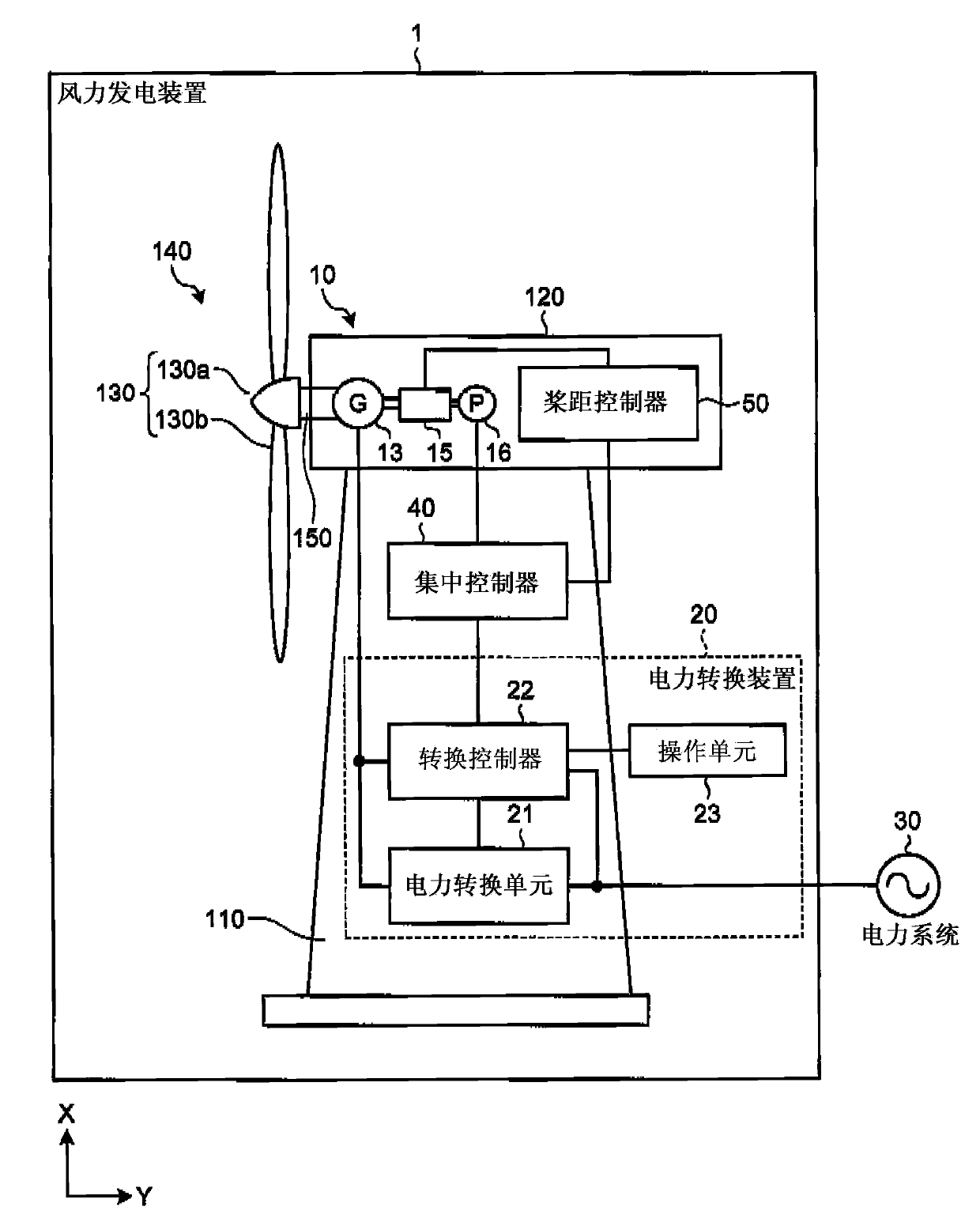
[0017] figure 1 is a schematic diagram showing the structure of the wind power generator according to the first embodiment. Such as figure 1 As shown in , a wind power generation device 1 includes a wind power generation unit 10 and a power conversion device 20 , and supplies power to a power system 30 . In order to understand the present invention easily, from figure 1 Some components are omitted. In the following description, in or...
PUM
 Abstract
Description
Claims
Application Information
PatSnap Eureka turns technology decisions into work you can execute. Powered by our Innovation Knowledge Graph, it runs expert workflows across engineering, life sciences, materials and intellectual property. Get your review-ready output in minutes.


