Method for restraining torque pulsation of permanent magnet synchronous motor

A permanent magnet synchronous motor, torque ripple technology, applied in motor generator control, electronic commutation motor control, control generator and other directions, can solve the complex non-sinusoidal distortion, magnetic density distribution is not completely sinusoidal, affecting the motor control performance and other problems, to achieve the effect of increasing the compensation current and improving the compensation effect.

Active Publication Date: 2013-10-30
DORNA TECH
View PDF3 Cites 21 Cited by
  • Summary
  • Abstract
  • Description
  • Claims
  • Application Information

AI Technical Summary

Problems solved by technology

Among them, non-sinusoidal distortion is the most complex
In fact, even if the permanent magnet synchronous motor is not demagnetized, due to design and manufacturing errors, the magnetic density distribution in t

Method used


Image

  • Method for restraining torque pulsation of permanent magnet synchronous motor
  • Method for restraining torque pulsation of permanent magnet synchronous motor
  • Method for restraining torque pulsation of permanent magnet synchronous motor

Examples


Embodiment 1

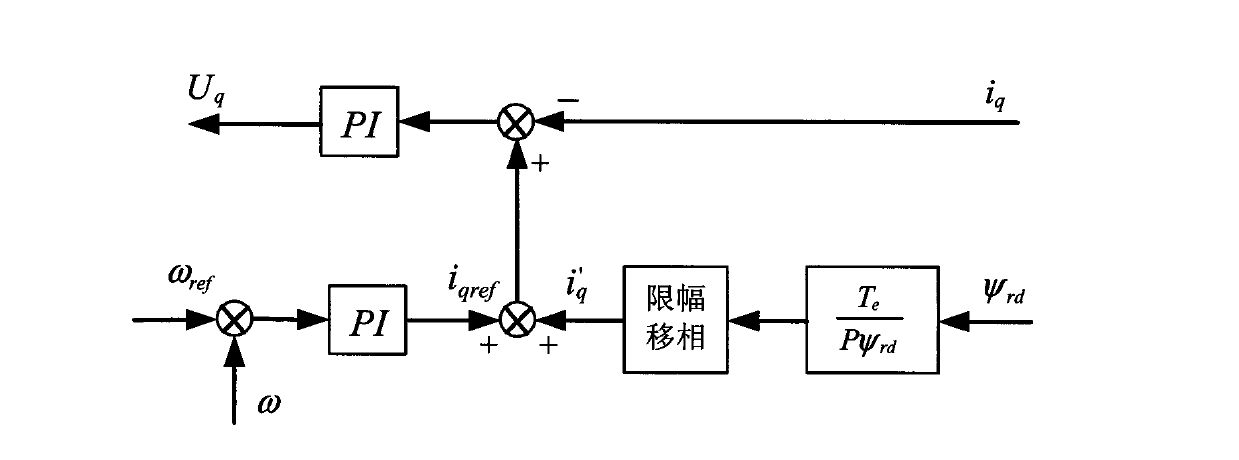
[0023] The method for suppressing the torque ripple of the permanent magnet synchronous motor provided by the present invention includes using the original reference signal and the q-axis current signal, and adopting the method of superimposing the q-axis current compensation to suppress the torque of the permanent magnet motor. The q-axis current compensation There are two method steps respectively:

[0024] (1) When the electromagnetic output torque T e Under a given condition, the q-axis compensation current can be calculated by the electromagnetic torque formula, and then superimposed with the original reference signal, then compared with the q-axis current and sent to the controller to output the q-axis voltage, the q-axis compensation current i' q The formula is:

[0025] i q ′ = T e Pψ rd

[0026] In the abov...

Embodiment 2

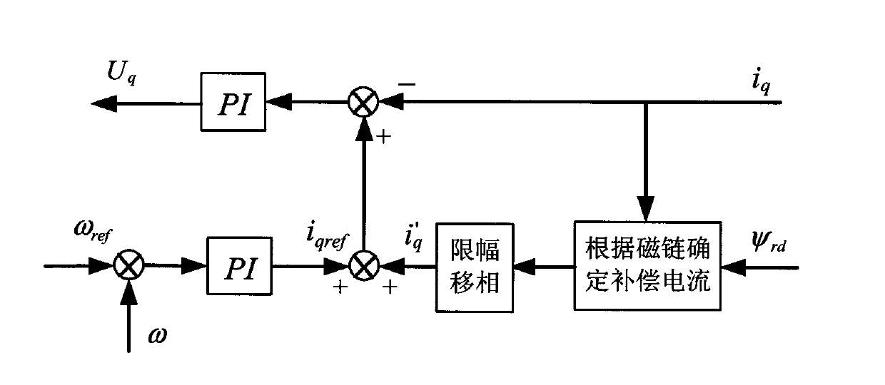
[0048] Since the first method is for a given given output torque T e , the compensation current i' of the q-axis can be accurately calculated q . Realize the current compensation, but not all occasions where the electromagnetic torque of the motor can be accurately known, the first method cannot be used to calculate the compensation current, so the method of determining and calculating the compensation current by flux linkage can be adopted. The circuit control block diagram is as follows figure 2 as shown,

[0049] At this time, i' in the control method q The formula of can be determined according to the flux linkage, and the formula is as follows:

[0050] i q ′ = β * ( ψ rd - ψ rd * ) ψ ...


PUM


Abstract

The invention discloses a method for restraining torque pulsation of a permanent magnet synchronous motor. Original reference signals and q axis current signals are adopted, and the method is characterized in that a superposition q axis current compensation method is adopted for restraining the torque of the permanent magnet motor. The q axis current compensation method can be conducted in the following two modes respectively: under the condition that the output torque Te is given, the q axis compensation current can be calculated on the basis of an electromagnetic torque formula; when the electromagnetic torque needed by the motor can not be accurately known, the compensation current can be determined according to a flux linkage formula. According to the method for restraining torque pulsation of the permanent magnet synchronous motor, the control performance of the permanent magnet synchronous motor is improved by increasing the compensation current, the good compensation effect is achieved through a phase shifting link, and through an amplitude limiting link, the compensation effect can be prevented from being affected when current glitches are large, and the protection function is achieved.

Description

technical field [0001] The invention relates to a technology for suppressing the torque ripple of a permanent magnet motor, in particular to a method for suppressing the torque ripple of a permanent magnet synchronous motor. Background technique [0002] In permanent magnet synchronous motor control, torque ripple affects the control performance of the motor. Through long-term research on torque ripple, people have summarized some of the reasons, among which the non-ideal sinusoidal waveform of the magnetic density is a very important factor, such as the cogging effect is also the result of the non-ideal air gap magnetic density. A torque ripple compensation control strategy based on the characteristics of flux density variation is proposed. The demagnetization of the permanent magnet causes three changes in the flux density waveform. Among them, non-sinusoidal distortion is the most complicated. In fact, even if the permanent magnet synchronous motor is not demagnetized,...

Claims


Application Information

Patent Timeline
IPC IPC(8): H02P21/05H02P21/14
Inventor 吕春松李社伟鲁杰爽肖曦
Owner DORNA TECH
Why Eureka
Try Eureka