In-cylinder pressure detecting device of direct injection type internal combustion engine

A direct-injection internal combustion engine and detection device technology, applied in fuel injection devices, special fuel injection devices, measuring devices, etc., can solve the problems of pressure detection accuracy reduction, piezoelectric element size reduction, and adverse effects of fuel flow, etc., to achieve Effects of suppressing overheating, expanding size, and improving pressure detection accuracy and durability

Active Publication Date: 2013-10-30
HONDA MOTOR CO LTD +1
View PDF11 Cites 4 Cited by
  • Summary
  • Abstract
  • Description
  • Claims
  • Application Information

AI Technical Summary

Problems solved by technology

[0010] In addition, in the structure described in Patent Document 2, the piezoelectric element is provided at the end of the injector facing the combustion chamber, and the piezoelectric element can be cooled by the fuel passing through the injector to prevent a temperature rise. When the piezoelectric element is provided on the outer surface of the small tip of the injector, there is a problem that the size of the piezoelectric element is reduced and the pressure detection accuracy is reduced. In addition, when the fuel passage at the tip of the injector is In the case where a piezoelectric element is provided on the inner surface or on the outer surface of the needle valve that cooperates with the fuel passage, the size of the piezoelectric element is still reduced and the pressure detection accuracy is reduced. problems that adversely affect the flow of fuel within the

Method used


Image

  • In-cylinder pressure detecting device of direct injection type internal combustion engine
  • In-cylinder pressure detecting device of direct injection type internal combustion engine
  • In-cylinder pressure detecting device of direct injection type internal combustion engine

Examples


no. 1 Embodiment approach

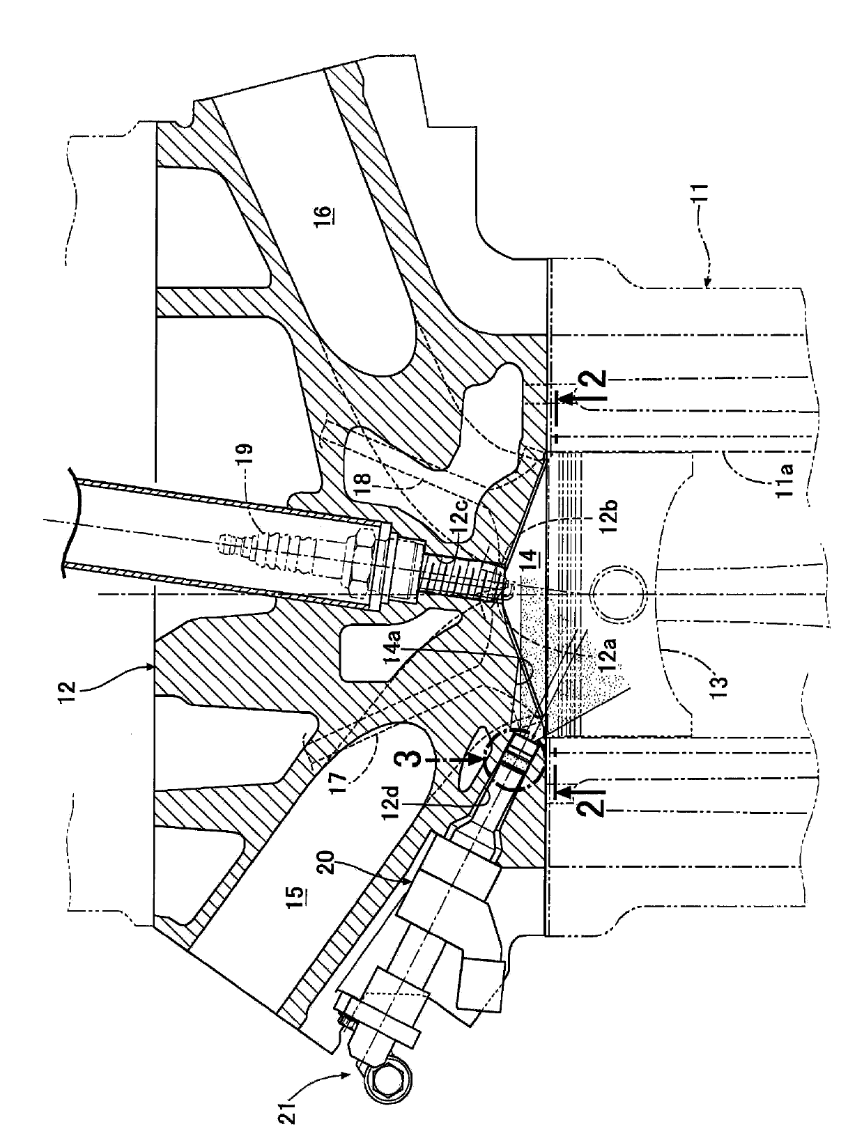
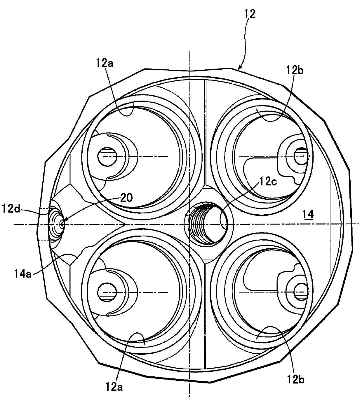
[0073] Such as figure 1 with figure 2 As shown, a cylinder head 12 is bonded to the upper surface of the cylinder block 11 of the direct fuel injection internal combustion engine, and a combustion chamber is formed between the upper surface of the piston 13 that is slidably fitted to the cylinder bore 11a and the lower surface of the cylinder head 12. 14. The two intake valve holes 12a, 12a connected to the intake port 15 and the two exhaust valve holes 12b, 12b connected to the exhaust port 16 open to the combustion chamber 14, and the two intake valve holes 12a, 12a are respectively The intake valves 17, 17 are opened and closed, and the two exhaust valve holes 12b, 12b are opened and closed by the exhaust valves 18, 18, respectively.

[0074] A spark plug 19 is mounted in a spark plug mounting hole 12 c formed in the center of the combustion chamber 14 . Further, a recessed portion 14a is formed at a position sandwiched between the two intake valve holes 12a, 12a of the...

no. 2 Embodiment approach

[0096] In the first embodiment, the pressure detection element 34 and the collar structure 35 are composed of separate members, whereas in the second embodiment, the pressure detection element 34 and the collar structure 35 are composed of a single member. According to this second embodiment, reduction in the number of components and simplification of the structure can be achieved.

[0097] Next, according to Figure 7 A third embodiment of the present invention will be described.

no. 3 Embodiment approach

[0099] In the first embodiment, the valve housing 31 and the collar structure 35 are composed of separate parts, but in the third embodiment, the collar structure 35 and the valve housing 31 are integrally formed. Therefore, the pressure detection element storage groove 31f formed on the outer surface of the valve housing 31 in the first embodiment is constituted by the tunnel-shaped output signal transmission member storage hole 31g in the third embodiment. The housing hole 31g penetrates through the inside of the valve housing 31 and the collar structure 35 which are integrally formed. According to the third embodiment, reduction in the number of components and simplification of the structure can be achieved.

[0100] Next, according to Figure 8 A fourth embodiment of the present invention will be described.


PUM


Abstract

In an in-cylinder pressure detecting device of a fuel direct injection type internal combustion engine, an annular pressure detecting element (34) is installed around a fuel injection hole (33b) at a position close to the tip end of an injector used to inject fuel into a combustion chamber. Since the pressure detecting element (34) is installed on the injector, it is not necessary to change the shape or structure of a cylinder head or the combustion chamber for installing the pressure detecting element (34), and since the pressure detecting element (34) can be cooled by fuel passing through the injector, the pressure detecting precision and durability of the pressure detecting element (34) can be improved. In addition, since the pressure detecting element (34) is disposed around the fuel injection hole (33b), the size of the pressure detecting element (34) can be maximally increased while preventing interference between the pressure detecting element (34) and fuel injected through the fuel injection hole (33b), so as to guarantee pressure detecting precision.

Description

technical field [0001] The invention relates to a cylinder pressure detection device of a fuel direct injection internal combustion engine. Internal combustion engines have injectors that inject fuel into combustion chambers. Background technique [0002] According to the following patent document 1, there is known such a tube pressure detection device: a protrusion is provided on the back side of the metal diaphragm provided at the end of the tube pressure sensor facing the combustion chamber of the internal combustion engine, and the deformation of the metal diaphragm is detected by the protrusion. The resulting load is transmitted to the pressure sensing element. [0003] In addition, according to the following patent document 2, there is known such a cylinder internal pressure detection device: the inner wall surface of the cylinder head facing the combustion chamber of the internal combustion engine, the end portion of the glow plug or the spark plug facing the combust...

Claims


Application Information

Patent Timeline
Patent Type & Authority Applications(China)
IPC IPC(8): G01L23/10F02D35/00F02D45/00F02M65/00G01L23/22
CPCY02T10/125F02B2075/125F02D35/023Y02T10/123F02M57/005F02B23/104G01L23/22G01L23/10F02M61/14F02M2200/247Y02T10/12F02M69/00
Inventor 赤崎修介山本裕司钵吕俊隆佐藤岳
Owner HONDA MOTOR CO LTD
Why Eureka
Try Eureka